1736/1738
Users Manual
22
Topology (Distribution System)
Select the appropriate system. A connection diagram for
the voltage test leads and current sensors is shown on the
Logger.
A diagram is also available with (Connection
diagram) from the Change Configuration menu.
Examples of these diagrams are shown on the following
pages.
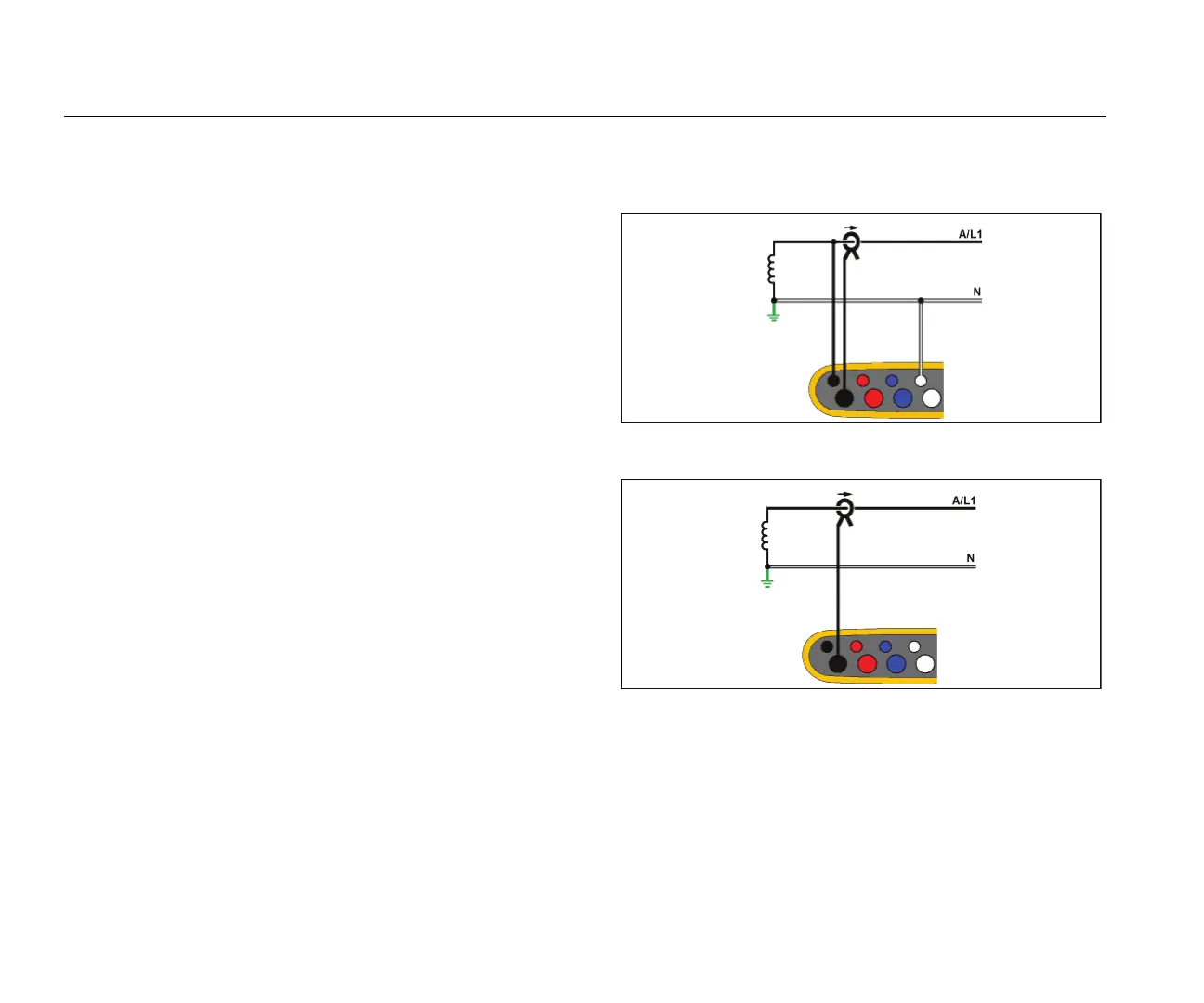
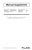
Single Phase
Example: Branch circuit at an outlet.
hcf040.eps
Energy Study
hcf041.eps
Load Study (no voltage measurement)