Fluke 19xC-2x5C
Users Manual
72
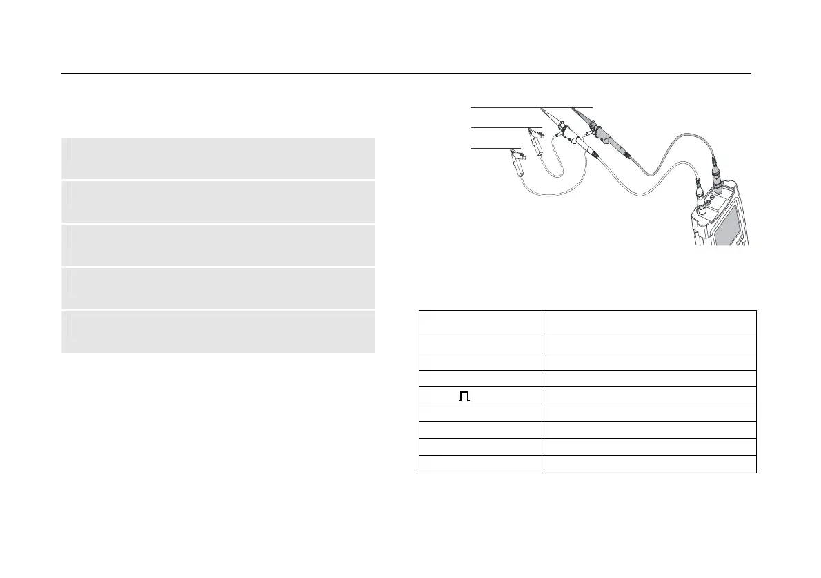
CAN Bus
Default probe setting 10:1. Use the Fluke 10:1 probes.
1 Connect the red probe to the test tool input A,
connect the grey probe to input B.
2 Connect the ground lead of the input A probe to
the CAN bus High (CAN_H)
3 Connect the probe tip of the input A probe to the
CAN bus Low (CAN_L)
4 Connect the ground lead of the input B probe to
the CAN bus ground (CAN_GND)
5 Connect the probe tip of the input B probe to the
CAN bus high (CAN_H)
Note
The bus normally has continuous data traffic.
CAN-H
CAN-L
CAN-GND
DB-9
BD2
6 / 3
7
5 / 5
3
14/11
2
Figure 38. CAN Bus Measurement Connections
Table 4. CAN Bus Tested Signal Properties
Signal Description
CAN Dom. H-L Dominant high to low level voltage
CAN Rec. H-L Recessive high to low level voltage
CAN-Level Common mode voltage
Data Bit width
Rise Rise time as % of bit width
Fall Fall time as % of bit width
Jitter Jitter distortion
Overshoot Overshoot distortion