Using The Bushealth Function
Input Connections and Tested Signals
6
73
RS-232 Bus & Modbus IEA-232/RS-232
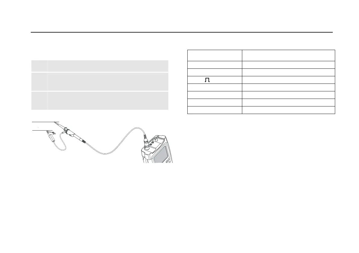
Default probe setting 10:1. Use the Fluke 10:1 probe.
1 Connect the red probe to the test tool input A.
2 Connect the probe ground lead to the RS-232
bus Signal Ground.
3 Connect the probe tip to the RS-232 bus TxD or
RxD.
x
or
x
GND
Figure 39. RS-232 Bus Measurement Connections
Table 5. RS-232 Bus Tested Signal Properties
Signal Description
V-Level High High level voltage
V-Level Low Low level voltage
Data Bit width
Rise Rise time as % of bit width
Fall Fall time as % of bit width
Jitter Jitter distortion
Overshoot Overshoot distortion
Note
Continuous data traffic is not ensured . See Data
Traffic on page 70