Fluke 19xC-2x5C
Users Manual
74
RS-485 Bus & MOD Bus IEA-485/RS-485
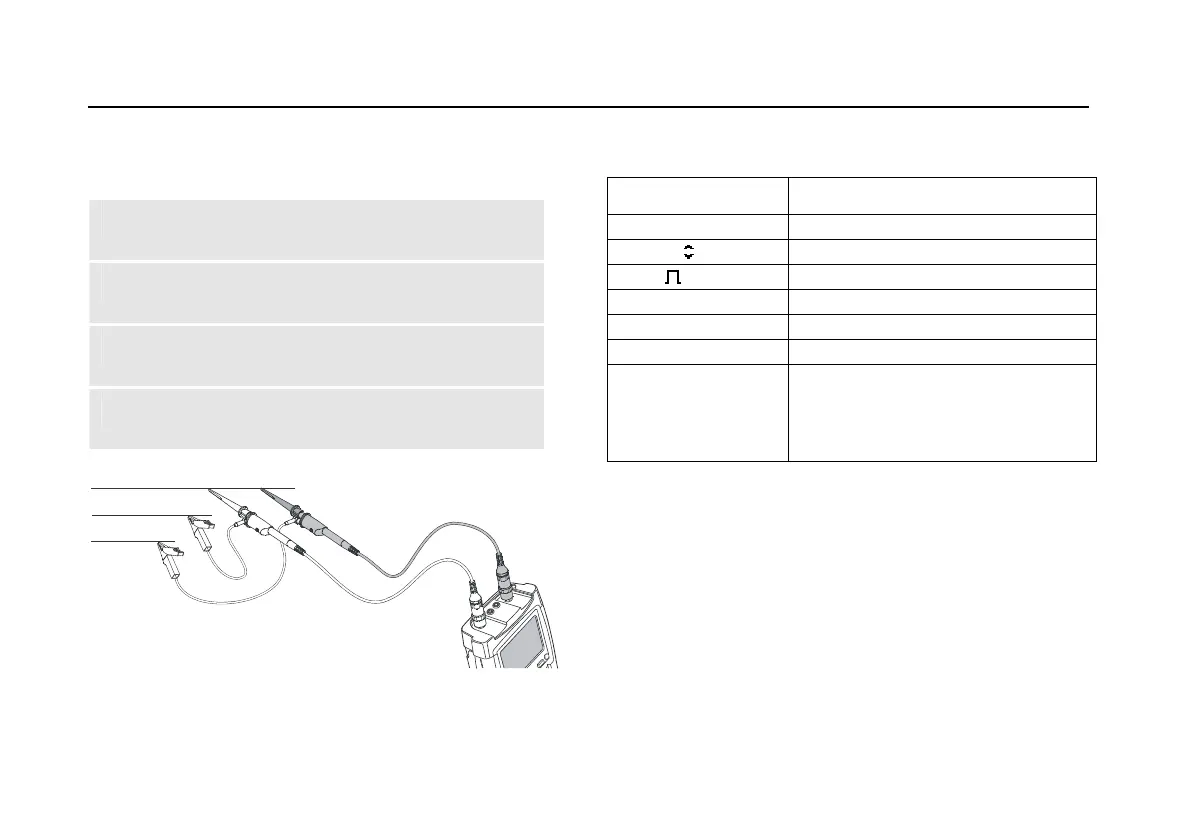
Default probe setting 10:1. Use the Fluke 10:1 probes.
1 Connect the red probe to the test tool input A
and the grey probe to input B.
2 Connect the ground lead of the input A probe to
the RS-485 bus RxD/TxD N (-)
3 Connect the ground lead of the input B probe to
the RS-485 bus cable shield.
4 Connect the probe tip of both probes to the
RS-485 bus RxD/TxD P (+)
DATA +
DATA -
DATA GND
Figure 40. RS-485 Bus Measurement Connections
Table 6. RS-485 Bus Tested Signal Properties
Signal Description
V-Offset High level voltage
V-Level Peak-peak voltage
Data Bit width
Rise Rise time as % of bit width
Fall Fall time as % of bit width
Jitter Jitter distortion
Signal Dist.
Overshoot
Signal distortion (Manchester
decoding, default setting)
Overshoot (NRZ decoding, can be
selected via limit setup)
Note
Continuous data traffic is not ensured . See Data
Traffic on page 70