Fluke 6500
Users Manual
4
Operating Features
Front panel description
The connectors, controls and indicators of the tester are
shown and listed below.
1 2
3
4
5
6 7 8
6500
APPLIANCE TESTER
GOGO
STOPSTOP
VISUAL
BOND
200 mA
BOND
25 A
INSUL-
ATION
I
SUB
LOAD/
LEAK
I
TOUCH
IEC
LEAD
AUTO
£
.
=
+
"
:
*
()
#
?/
%&
SHIFT
SPACE
Q
WE R T
UIO
L
ASDFGHJK
Z
CVBNM
1234567890
CAPS
PC/PRINT
YES MEM
NO
SET
UP
,
P
SWITCH ON APPLIANCE FOR ALL TESTS
IEC
BOND 25A/200mA
TOUCH PROB E
INSULATION PROBE
CLASS II
PROBE PE LV
TEST SOCKET
230V 50Hz / MAX 13A
BOND ZERO
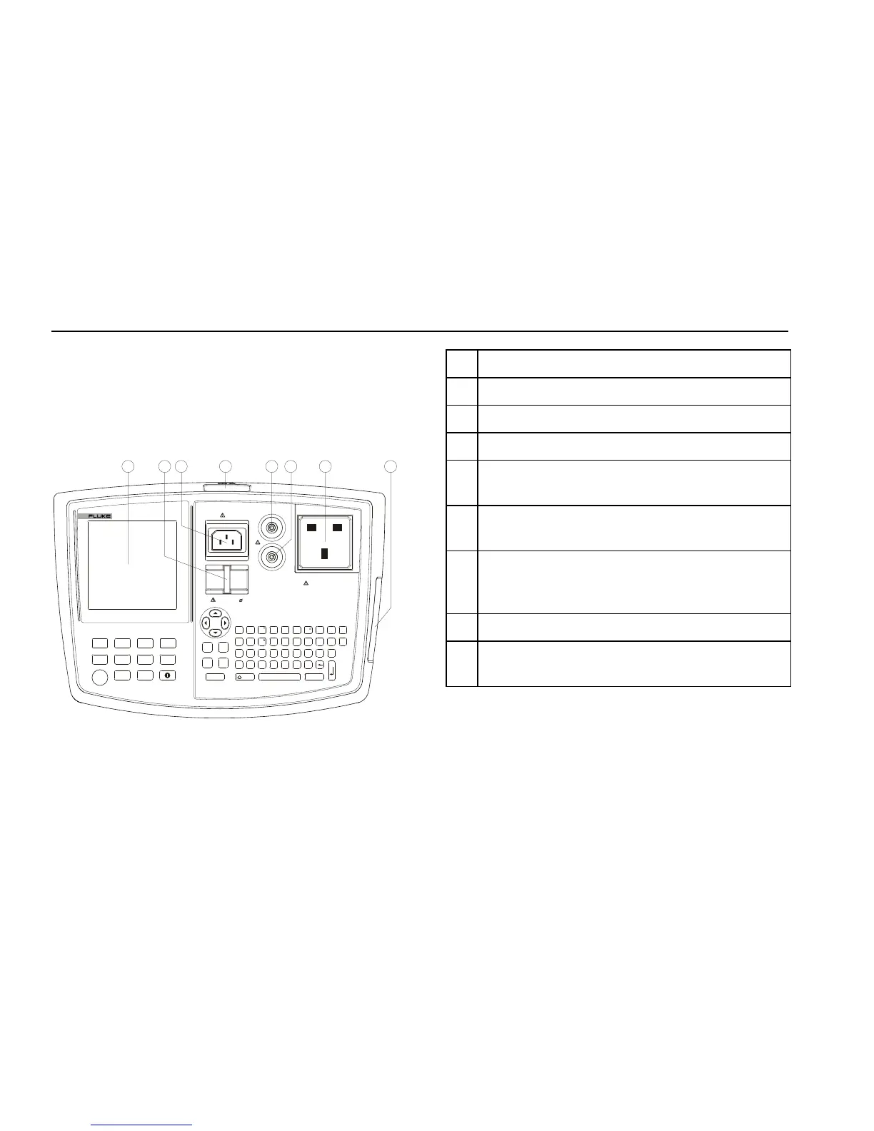
Figure 1. Fluke 6500
No. Description
1 Liquid Crystal Display (LCD).
2 Earth bar to zero the Earth Bond test lead.
3 Socket to connect IEC lead for IEC Lead test .
4 Serial RS-232 Port to connect the Fluke printer,
Fluke barcode scanner, or a computer.
5 Socket to connect test lead and crocodile clip for
Earth Bond test.
6 Socket to connect test probe for Insulation test,
Touch Current test, Substitute Leakage test and
PELV test.
7 Socket to connect the appliance to be tested.
8 Slot to insert a Type I Compact Flash Memory
Card.