Process Calibrators
Verification
31
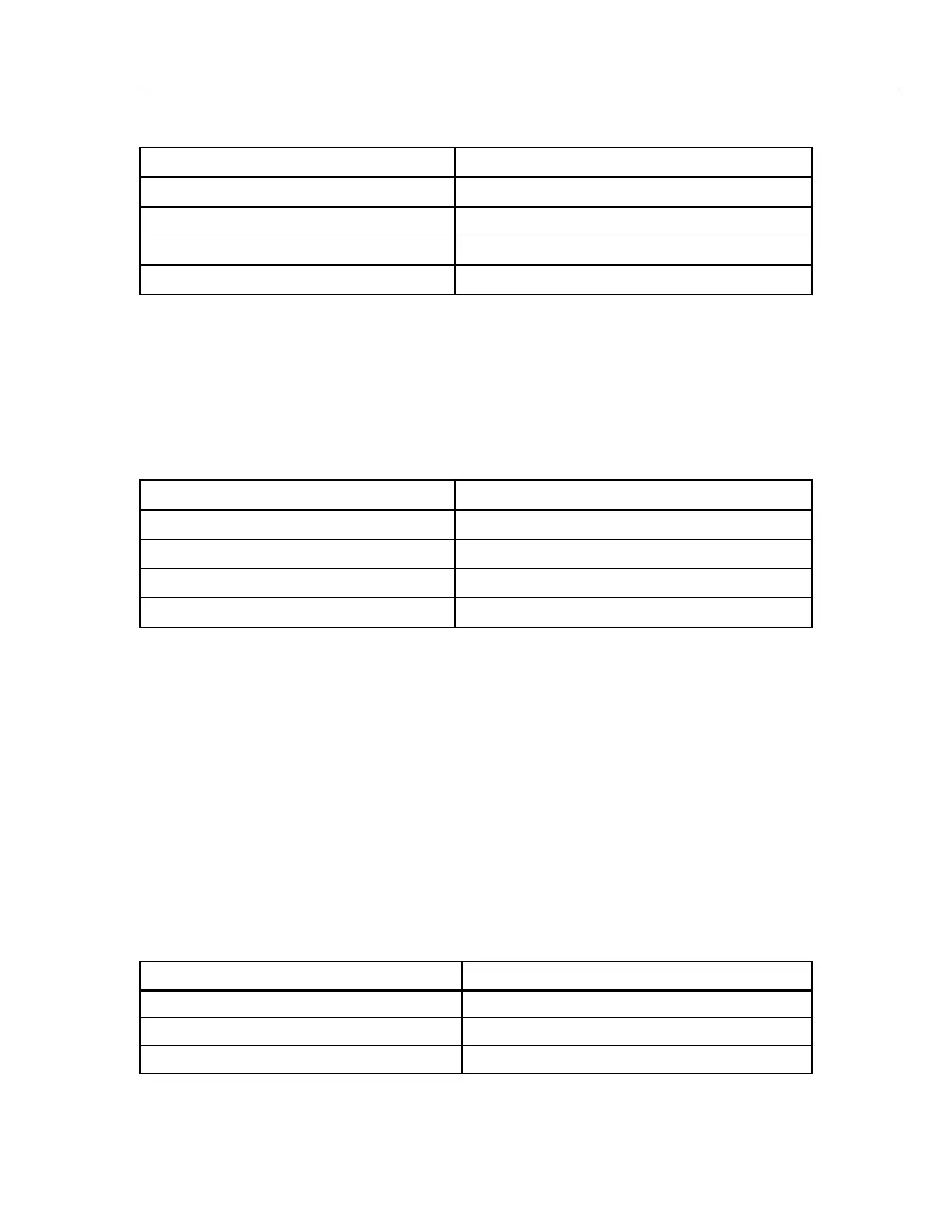
Table 40. 712 Verification Resistance Values
5520A Outputs (Ω) 4-wire 712 Readings (Ω)
5.00 4.899 to 5.101
300.00 299.825 to 300.175
1500.0 1499.525 to 1500.475
30000.0 2999.15 to 3000.85
11. Make 2-wire connections on the 712 to 4-wire connections on the Fluke 8508A. Set
the Fluke 8508A to measure 4-wire resistance.
12. Push until OUTPUT is displayed.
13. Set the 712 to output the resistance values in Table 41. Verify that the Fluke 8508A
readings are within the limits shown.
Table 41. 712 Verification Outputs
712 Outputs (Ohms) Fluke 8508A Readings (Ohms)
5.00 4.899 to 5.101
300.00 299.825 to 300.175
1500.0 1499.525 to 1500.475
30000.0 2999.15 to 3000.85
14. Disconnect all connections to the 712. The 712 verification test is complete.
714 Verification (Earlier than V2.0)
Thermocouple Measure Verification
1. Push the
key to turn on the 714 Calibrator. Push the key and the key so
that the display indicates:
INPUT xx.x °C
where xx.x is some variable number; or OL (overload) may be indicated.
2. Push the
key to measure Type J thermocouple and connect the Type J
thermocouple test lead from the TC jack of the Fluke 5520A to the TC jack on the
714 Calibrator, observing correct polarity.
3. Set the Fluke 5520A to output in Type J thermocouple, push the Okey, and set the
5520A to the settings in Table 42, verifying the display readings on the 714:
Table 42. 714 Thermocouple Measure Verification
Fluke 5520A Fluke 714
-200.00 °C -200.9 °C to -199.1 °C
0.00 °C -0.7 °C to +0.7 °C
1200.00 °C 1199.3 °C to 1200.7 °C
1.888.610.7664 sales@GlobalTestSupply.com
Fluke-Direct.com

 Loading...