Process Calibrators
Verification
39
DC Current Measure Verification
1. Push key on the 715 Calibrator. Display should indicate closely to:
INPUT -25.00 mA %
2. Push the key and the display should change to:
INPUT 0.000 mA
3. Connect a test lead from Red AUX terminal of the 5520A to the Fluke 8508A I+
terminal.
4. Connect a test lead from Black AUX terminal of the 5520A to the 715 Calibrator
Com terminal.
5. Connect a test lead from I- terminal of the Fluke 8508A to the 715 Calibrator mA
terminal.
6. Adjust the 5520A if necessary so that the current shown on the Fluke 8508A is the
same as the 5520A values shown in Table 59.
7. Verify that the display readings on the 715 Calibrator are within the limits.
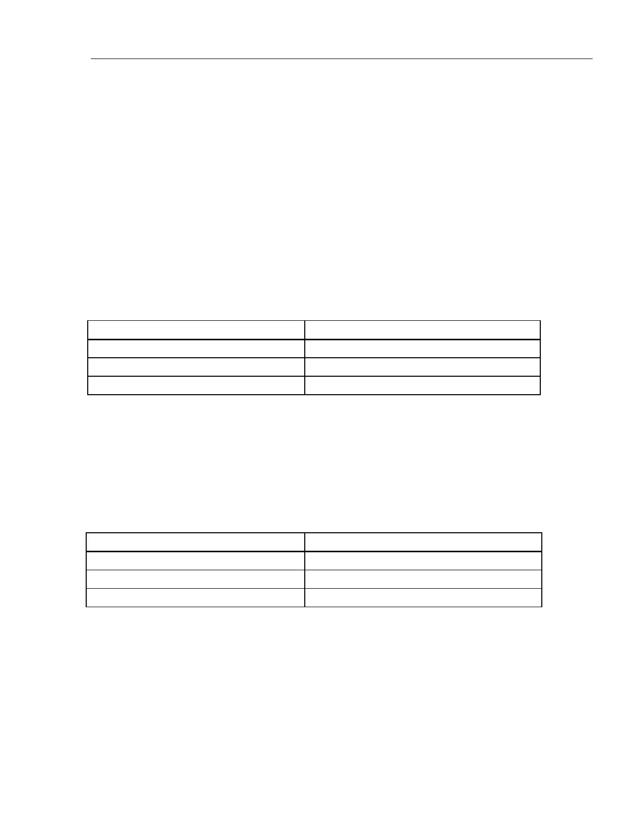
Table 59. 715 DC Current Measure Verification
Fluke 5520A Fluke 715
24.0000 mA 23.993 mA to 24.007 mA
12.0000 mA 11.996 mA to 12.004 mA
4.0000 mA 3.998 mA to 4.002 mA
DC Voltage Measure Verification
1. Push the key on the 715 Calibrator. Display should change to:
INPUT 0.000 V
2. Connect test leads from the output NORMAL jacks of the Fluke 5520A to the voltage
jacks on the 715 Calibrator (black to COM jack and red to the V jack).
3. Set the Fluke 5520A for the voltage settings in Table 60, and verify the display
readings on the 715 Calibrator.
Table 60. 715 DC Voltage Measure Verification (25.0000 to 0.0000 V)
Fluke 5520A Fluke 715
20.00000 V 19.996 V to 20.004 V
10.00000 V 9.997 V to 10.003 V
0.0000 V -0.002 V to +0.002 V
4. Push the key on the 715 Calibrator. Display should indicate closely to:
INPUT 0.00 mV
5. Set the Fluke 5520A for the mV settings in Table 61, and verify display readings on
the 715 Calibrator.
1.888.610.7664 sales@GlobalTestSupply.com
Fluke-Direct.com

 Loading...