71X Series
Calibration Manual
56
Leak Test Verification
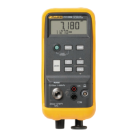
1. Seal off the pressure sensor input port.
2. Using the fine adjust knob, pressure-vacuum switch and internal pump, set the
Calibrator to the values in Table 68. Let the unit sit for one minute, then record the
displayed value.
3. Wait for one more minute, then record a second reading. The difference between the
first and the second reading is the leak rate.
Table 68. 719 Leak Test Verification
719 30G 719 100G
Adjusted Pressure Maximum Leak Rate Adjusted Pressure Maximum Leak Rate
-10.00 PSI 0.05 PSI/min -10.00 PSI 0.1 PSI/min
3.00 PSI 3.00 PSI
30.00 PSI 100.00 PSI
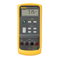
mA Measure Verification
The lower display should indicate:
0.000mA
1. Connect a test lead from Red AUX terminal of the 5520A to the Fluke 8508A I+
terminal.
2. Connect a test lead from Black AUX terminal of the 5520A to the Calibrator COM
terminal.
3. Connect a test lead from I- terminal of the Fluke 8508A to the Calibrator mA
terminal.
4. Adjust the 5520A so that the current shown on the Fluke 8508A is the same as the
5520A values shown in Table 69.
5. Verify that the display readings on the Calibrator are within the limits.
Table 69. 719 mA Measure Verification
Fluke 5520A Fluke 719
4.0000 mA 3.997 mA to 4.003 mA
12.0000 mA 11.996 mA to 12.004 mA
24.0000 mA 23.993 mA to 24.007 mA
6. Disconnect the test leads and turn off the 719 Calibrator.
1.888.610.7664 sales@GlobalTestSupply.com
Fluke-Direct.com

 Loading...