8588A/8558A
Operators Manual
14
Rear-Panel Features
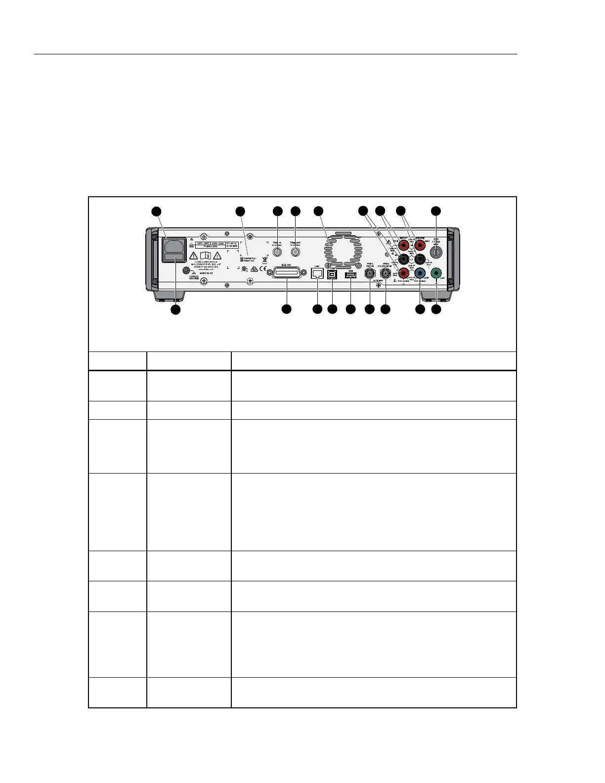
Rear-panel features (including all terminals, sockets, and connectors) are shown
and described in Table 4.
Note
The rear-panel terminals do not have Visual Connection
Management active terminal illumination.
Table 4. Rear-Panel Features
123
45 7
69
8
10
11
12
13
14151617
18
3
iei002.emf
Number Name Function
AC power input
connector
A grounded male three-prong connector for the mains power cord
that also houses the mains fuse.
Serial number The Product Serial Number.
TRIG IN
This co-axial BNC socket can be used to trigger a measurement
when external triggers are enabled. The trigger in signal can be
either a TTL or Bipolar, with either a negative or positive slope. See
Triggering Measurements.
D TRIG OUT
This co-axial BNC socket outputs a signal when a specified
measurement event occurs. The signal may be a TTL edge or a
square wave which is active during a particular process. This signal
is used to synchronize external equipment to the Product and is
comparable to the HP/Agilent/Keysight 3458A EXT OUT output. See
Input Terminals Selection.
E Fan access holes
Access holes for the internal fan. Air is expelled from the Product for
internal cooling through these holes. See Cooling Considerations.
F
INPUT, A HI and
LO
A pair of five-way binding posts for current measurements. Signals
up to 2 A rms can be applied to these terminals.
G
INPUT, V HI and
LO
A pair of five-way binding posts for voltage, ohms, capacitance, 2-
wire PRT, and thermocouple measurements. On the 8588A, these
binding posts also connect to the output of external current shunts.
Frequency can be measured via these terminals. Signals up to
1050 V rms can be applied to these terminals.
H
SENSE, V HI and
LO
A pair of five-way binding posts for 4-wire resistance measurements.
They are the sense terminals in 4-wire Ω and 3- and 4-wire PRT.
 Loading...


