True-rms Multimeter
The Meter's Features
13
aom1_af.eps
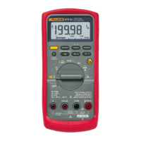
Figure 1. Display Features
Table 5. Display Features
Number Feature Indication
Y Polarity indicator for the analog bar graph.
A
Trig
Y
Positive or negative slope indicator for
Hz/duty cycle triggering.
B X The continuity beeper is on.
C W Relative (REL) mode is active.
D g Smoothing is active.
Number Feature Indication
E -
Indicates negative readings. In relative
mode, this sign indicates that the present
input is less than the stored reference.
F Z
Indicates the presence of a high voltage
input. Appears if the input voltage is 30
V or greater (ac or dc). Also appears in
low pass filter mode. Also appears in cal,
Hz, and duty cycle modes.
G
RS
AutoHOLD is active.
H
S
Display Hold is active.
I p
Indicates the Meter is in Peak Min Max
mode and the response time is 250 µs.
J
m
MAX
MIN
AVG
Indicators for minimum-maximum
recording mode.
K K
Low pass filter mode. See “Low Pass
Filter.
L b
The battery is low. XWWarning: To
avoid false readings, which could lead
to possible electric shock or personal
injury, replace the battery as soon as
the battery indicator appears.