Model 787
Calibration Manual
28
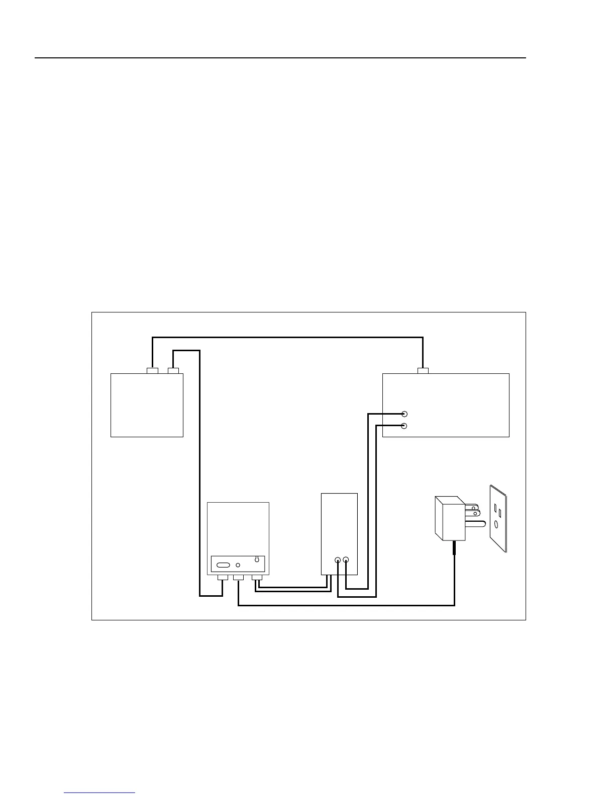
3. Plug the battery connector from the UUT into the connector on the battery door of
the Calibration Module.
4. Attach the battery door on the Calibration Module cable to the UUT.
5. Connect Calibration Module to the appropriate communication port on the PC, using
an RS-232 9-pin, null modem cable. (See Figure 13.)
Note
The calibration procedure does not support the UUT port on the Fluke
5500A and 5520A calibrators.
6. Connect the battery eliminator to the Calibration Module, and plug the battery
eliminator into an AC outlet.
7. Turn the rotary switch on the UUT to the
K position and warm up the UUT for five
minutes.
8. Start MET/CAL and select the calibration procedure that matches the calibrator and
multimeter in use.
PC
787
Calibration
Module
UUT
Battery Eliminator
(See Table 2.)
Calibrator
Outlet
IEEE-488 Connection
RS43 9-Pin
Null Modem Cable
LT015F.EPS
Figure 12. Calibration Connections for the 787 ProcessMeter