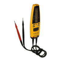
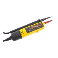
T6-1000/T6-600
Service Information
10
Low Battery Indicator
To verify the correct operation of the low battery indicator:
1.
Remove the Tester batteries.
2.
Set the dc power supply to 3.0 V. Apply this voltage to the Tester battery terminals and observe the correct polarity.
3.
Set the Tester to the resistance measurement mode.
4.
Verify that four bars (full battery) show inside the battery indicator on the Tester display.
5.
Set the calibrator to 100 Ω. Apply this resistance to the Tester probes.
6.
Reduce the dc power supply voltage down to 2.3 V.
7.
Wait approximately 10 seconds for the battery indicator to update.
8.
Verify that 0 bars (empty battery) show inside the battery indicator on the Tester display.
9.
Verify that the Tester display reading is 97 Ω to 103 Ω.
10.
Turn off the Tester.
11.
Disconnect the dc power supply leads from the Tester.
12.
Disconnect the calibrator from the Tester.
13.
Reinstall the Tester batteries.
Battery Door Circuit
To verify the battery door circuit operates correctly:
Note
During this test, do not use a sharp test probe to contact the battery door pad. The pad can be
easily damaged.
1.
Set the 8846A to ACI and 1 mA range.
2.
Set the 8846A resolution to LOW (MEAS SETUP > RESOLUTION > LOW). This hides the two least significant digits that are
noisy.
3.
Set the calibrator to 20 V, 55 Hz.
4.
Connect the test equipment as follows:
a. 8846A 400 mA jack to the battery door probe dock spring.
b. calibrator NORMAL LO to the 8846A LO jack (current).
c. calibrator NORMAL HI to the battery door pad.
5.
Set the calibrator to OPERATE.
6.
Verify that the 8846A reads between 21 μA and 15 μA (0.0210 to 0.0150).
7.
Change the calibrator frequency to 1 kHz and confirm the calibrator is in OPERATE mode.
8.
Verify that the 8846A reads between 112 μA and 68 μA (0.1120 to 0.0680).
9.
Set the Calibrator to STANDBY.
10.
Disconnect the battery door from the test instruments and reinstall it onto the Tester.

 Loading...