FMUSER INTERNATIONAL GROUP INC. 广州市汉婷生物技术开发有限公司
9
5.3 Power Supply
The RDS encoder can be supplied from any power supply, which delivers a voltage between 8 and 20 V DC and a
current of at least 200 mA. The RDS encoder has polarity protection and own voltage stabilizer. The central
conductor of the power supply connector is positive (+).
The JP1 jumper affects the analogue part supply voltage. The higher supply voltage the higher MPX signal level can be
processed. Stabilized power supply and care about right polarity is required if the JP1 is set to 2-3.
Note: After first power-up the RDS encoder will start to generate the RDS signal with factory default values
(PS: * RDS *, PI: FFFF). There is no need to configure anything to turn on the RDS subcarrier.
When attempting to set-up a unit that was already placed in operation before, the user should apply the
initialization first (chapter 11.2 or Windows control software help).
5.4 Level and Phase Adjustment
5.4.1 RDS signal output level
Note: There is no universal setting for the RDS level. Due to different input sensitivity of different FM broadcast
equipment it's preferred always to check and adjust the RDS level.
The right level should be between 2 and 11 % of the audio signal, measured in peak-to-peak values. Recommended
value is about 4 to 5 %, which results in 3.4 kHz deviation of the FM carrier. Don’t forget that the maximum total FM
carrier deviation with RDS and MPX signal is 75 kHz. Adjusting higher RDS level results in better RDS reception in
areas with weak signal coverage but the MPX (audio) level must be decreased a little to meet the total deviation limit.
The deviation range of the FM carrier caused by RDS/RBDS is 1.0 to 7.5 kHz.
The deviation range of the FM carrier caused by stereo pilot tone is 6.0 to 7.5 kHz.
The overall peak frequency deviation shall not exceed 75 kHz.
5.4.2 Phase adjustment for stereo transmission
The phase adjustment is made using the Windows control software or using the PHASE= command. Make sure the
external synchronization is enabled (check the command EXTSYNC or the item Clock source on the System card in
the Windows control software which must be set to Auto).
1. Fetch pilot or MPX signal to the RDS encoder. The LED2 will indicate that the pilot tone is present.
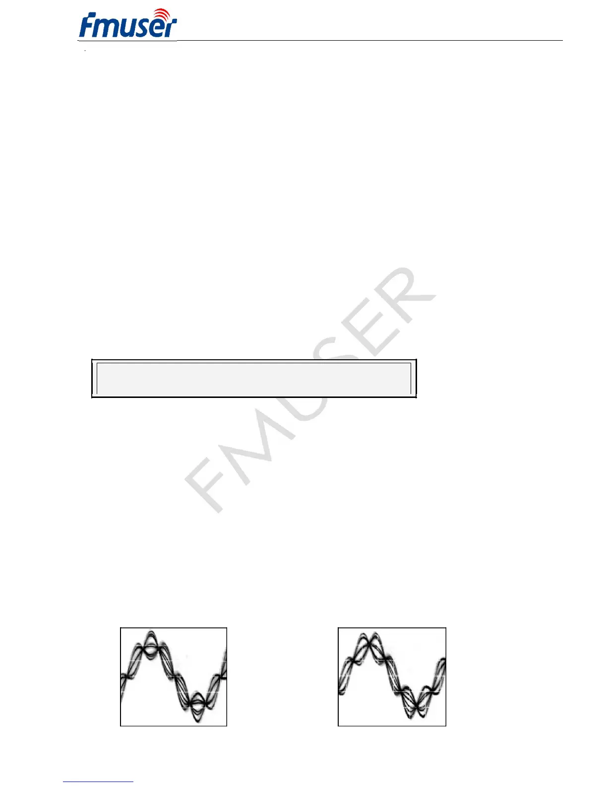
2. Adjust right phase shift (0 or 90 degrees phase shift between 19 kHz pilot tone and 57 kHz RDS subcarrier,
measured on transmitter input, see the oscillograms). The phase adjustment would be difficult without an
oscilloscope or specialized measuring instrument. Never mind if you don't have this equipment. It’s also possible
to set very low RDS level (when the signal strength is near error limit) and set the minimal error rate by adjusting
the phase.
Some experiments performed in the field show that the conditions of RDS reception are not too much affected
by the phase criterion. However, similar experiments have shown that right phase shift adjust offers a better
behaviour of audio receivers, and notably the residues of audio intermodulation which can sometimes be
observed, but with the aid of professional instruments only.
Conclusion: The phase adjustment is only optional and you may skip this step. Make sure the pilot tone is
indicated on the RDS encoder by the LED2.
Oscillograms
Pilot and RDS in phase
(0 degrees phase shift)
Pilot and RDS in quadrature
(90 degrees phase shift)