FMUSER INTERNATIONAL GROUP INC. 广州市汉婷生物技术开发有限公司
52
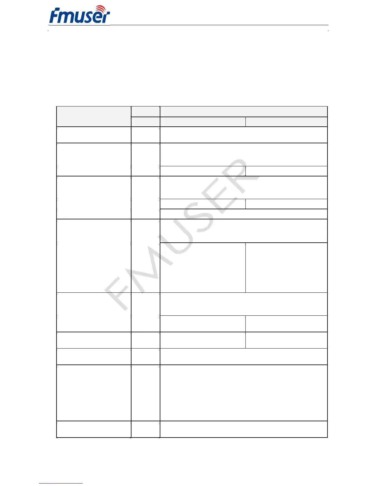
14.3 Troubleshooting
The RDS encoder has been designed to make its use as easy and painless as possible. However, success depends
upon a number of settings and things working together correctly. While correcting problems is usually quite simple,
the difficulty lays in knowing where to look.
Factory default settings assure right operation after first power-on. This section of the manual is designed to assist
you in determining the cause of problems that may occur so they can be fixed quickly.
Windows control software
Terminal
No RDS output, no LED
5.3
RDS output connected to right input of the transmitter?
Adjust higher RDS level or higher input sensitivity on the transmitter.
5.4.1
RDS generator switched on?
Options – Special – Switch on RDS
Make sure all connectors are seated completely and where possible,
use screws to fix the connection.
communicate with PC and
Make sure you have selected right COM port.
the LED does not indicate
Options – Preferences – List...
Try the unit with different cable and different PC.
Baudrate differs from the unit configuration.
Addressing is enabled and the unit is unselected.
the LED indicates that data
9.2.4
No header communication is active.
* Try after disabling the
11.6
Autodetect port speed options
12.2
Options – Special – Assign unit
Preferences and clicking on
<ESC><ESC><ESC><Enter>
any Send button or using
Hyperterminal and typing a
Radiotext stopped working
The RT service is not included in the Group sequence. This may occur
also after firmware update to version 1.5b. The Group sequence is a
although I’m sure that it’s
new feature that needs to be initialized.
enabled and entered
Options – Special – Group
sequence – Default, Store.
Pilot tone is fed to the unit
5.1
System sheet – Clock Source:
but it is not indicated.
5.4.3
Auto, Store
The unit loses time and date
4.1
Replace the on-board battery.
The unit is connected in loopthrough mode and the MPX level
exceeds 3.3 V pp but the JP1 is set to 1-2 instead of 2-3.
The audio is distorted.
5.1
The unit is not connected in loopthrough mode but JP2 was
forgotten on the board. Remove the jumper.
There is a whistling in the
5.2
The RDS level considerably exceeds maximum value allowed.
audio.
5.4.1
Adjust lower RDS level. Use an FM analyzer for the best result.
Applied input of the transmitter is not suitable for RDS. Follow
the transmitter documentation.
The unit is connected in loopthrough mode but JP2 is left open (not
present). Place the jumper on the JP2 position.