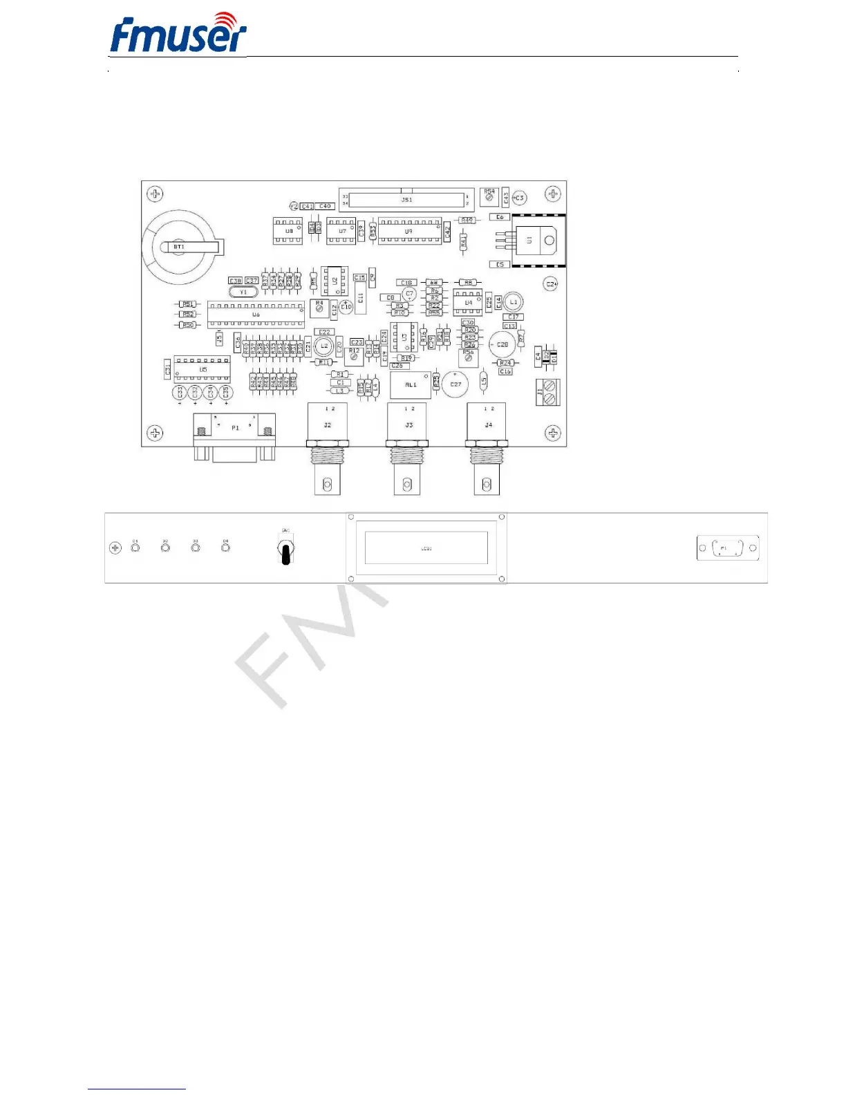
P1 - RS-232 Interface
9pin D-SUB male (DTE) connector:
1: Not used / +5 V
2: Receive Data (RDS encoder)
3: Transmit Data (RDS encoder)
4: Connected to pin 6
5: Ground
6: Connected to pin 4
7: Connected to pin 8
8: Connected to pin 7
9: Not used
J1 - Power supply
BT1 - Lithium battery 3 V for real time backup
Estimated endurance is 10 years. Replace
by CR2032 type.
4.3 Adjustable Elements
R56 - Output MPX signal level adjust
R12 - Output RDS signal level adjust
R4 - 19 kHz free running oscillator adjust (section 5.4.3)
4.4 LED Indicators
D1
- Poewr LED
D2
- TA LED
D3
- Pilot tone indication / Firmware update
D4
- Operation / Receive data / Error
Note: EEPROM memory that is used for RDS data storage does not require any voltage to hold the data.