FMUSER INTERNATIONAL GROUP INC. 广州市汉婷生物技术开发有限公司
7
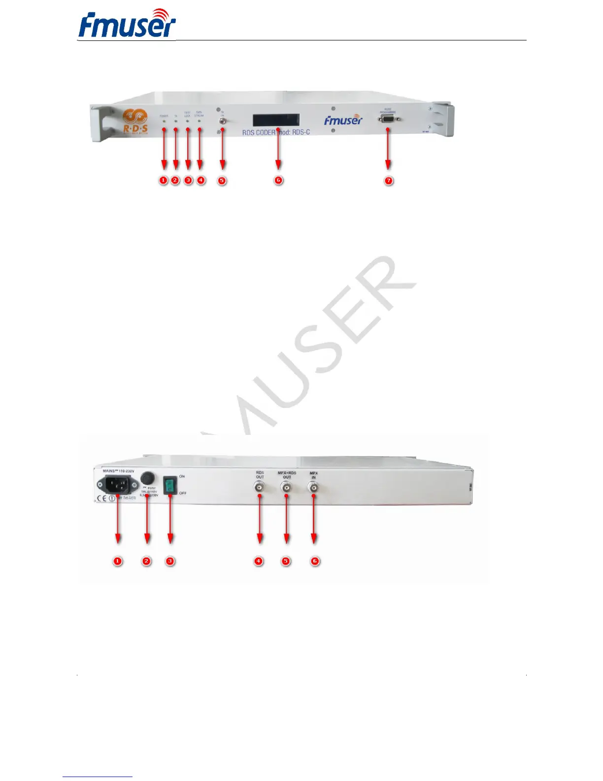
Front Panel Illustration:
1. Poewr LED
2. TA LED
3. Pilot tone indication / Firmware update
4. Operation / Receive data / Error
5. External TA/EON1TA switch
6. Screen display
7. RS-232 Interface
9pin D-SUB male (DTE) connector:
10: Not used / +5 V
11: Receive Data (RDS encoder)
12: Transmit Data (RDS encoder)
13: Connected to pin 6
14: Ground
15: Connected to pin 4
16: Connected to pin 8
17: Connected to pin 7
Rear Panel Illustration:
1. AC 110V-230V Power Input
2. FUSE
3. Power Switch
4. RDS OUT
5. MPX+RDS OUT
6. Pilot or MPX Input