32
Installation and Operation Manual
These FoamPro systems are designed to be easy to diagnose and service. There are several major components.
Servicing the system involves isolation of the failed component and replacing it. There are no user serviceable
internal components. Due to the reliable nature of modern electronics, most failures are traced to faulty cables or
wiring problems. A diagnostic mode is built into the system to help isolate problems.
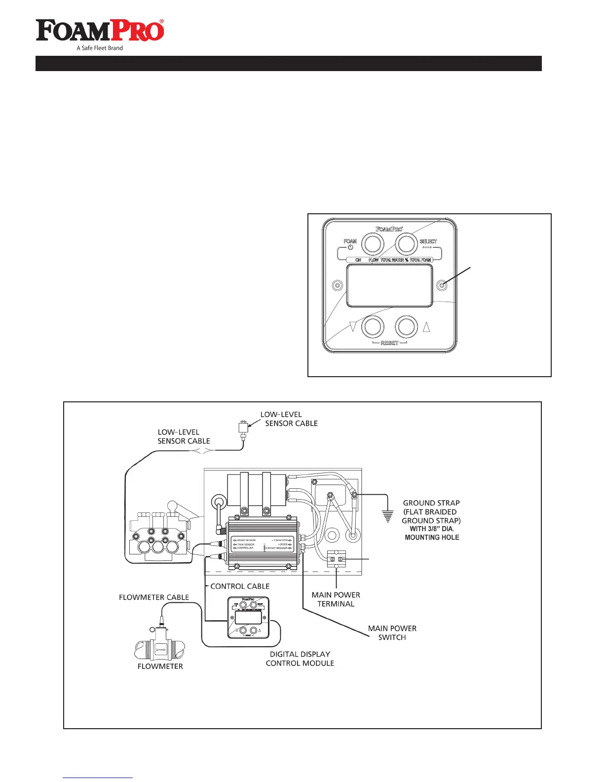
Figure 29. FoamPro 2002/2024 Electrical Wiring Diagram
ENTERING DIAGNOSTIC MODE
Diagnostic mode is entered by removing the center
screw and o-ring on the right-hand side of the Digital
Display Control Module (See Figure 28) using a 3/32
inch Allen wrench. Once the screw is removed, press
and release the switch located under the screw.
To exit the diagnostic mode, press and release the
switch again. “FRC or HYPRO” will appear on the display
followed by a zero after several seconds. REPLACE THE
COVER SCREW AND O-RING WHEN DONE.
Cover Screw
to be removed
Figure 28. Diagnostic Switch Location
12 Troubleshooting
HELLO
TO BATTERY SWITCH