14
Installation and Operation ManualInstallation and Operation Manual
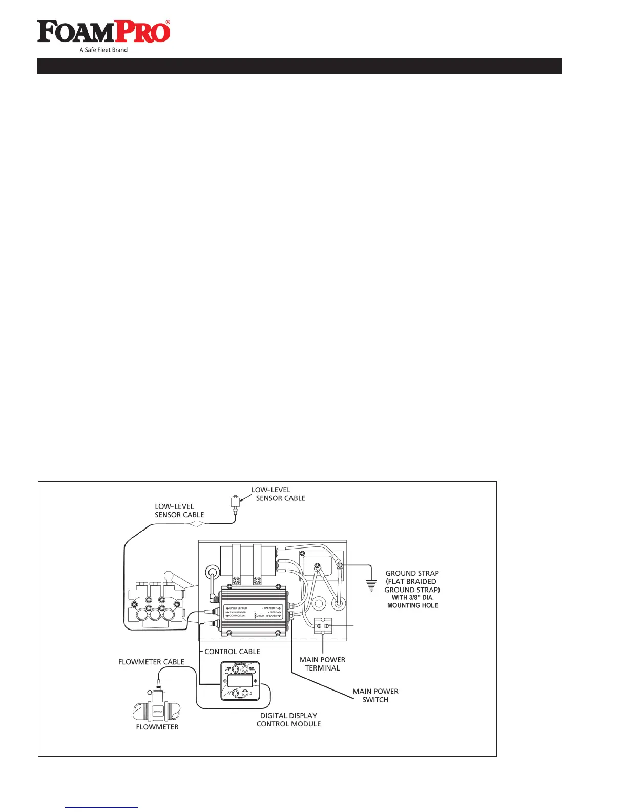
ELECTRICAL CONNECTIONS
Follow the system electrical diagram (Figures 13,14 and
30) for proper hookup of each of the electrical components.
Complete molded cable sets are provided with each
FoamPro system to make all the necessary connections.
The cables are color coded and “indexed” so they only go
in the correct receptacle and they can only go in one way.
DO NOT FORCE MISMATCHED CONNECTIONS. The
system can only perform when the electrical connections
are sound, so make sure each one is right.
SOME THINGS TO KEEP IN MIND
• DO NOT hook up the main power cables until all
connections are made to each of the electrical
components. The last connection should be the power
cable to the foam pump/motor base assembly.
• WARNING: This system contains a capacitor
on the input power. Connect the leads with the
battery off or disconnected. Current will flow even
with the circuit breaker off.
• DO NOT cut molded cables.
• Power must be supplied directly from the apparatus
battery without any connections to other high power
Figure 13. FoamPro 2002/2002HP/2024 Electrical Wiring Diagram
devices, such as primer pumps, hose reels, auxiliary
starters, light bars, et. with its own disconnect switch,
or a switch or contactor actuated by the battery
disconnect switch, PTO or other device.
• Provide at least the following amounts of electrical
power from the battery to the main power terminal:
2001 12 VDC requires 41 amps;
2002 or 2002HP 12 VDC requires 60 amps;
2001 24 VDC requires 22 amps;
2002 or 2002HP 24 VDC requires 30 amps;
2024 24VDC requires 60 amps.
Use proper wire size from the system terminal directly
to the battery as described on page 17.
• The S1xx-xxxx systems are designed for 12-volt,
negative-ground systems only. The S2xx-xxxx
systems are designed for 24-volt, negative-ground
systems only.
• Do not mount radio transmitter or transmitter cables in
direct or close contact with the FoamPro unit.
• Connect ground strap with 3/8” mounting hole to
chassis frame.
• Use care when installing molded cables. Count
pins or check color codes before connecting.
7 Electrical Equipment Installation
TO POSITIVE BATTERY CONNECTION,
BATTERY SWITCH RELAY,
OR CONTACTOR