8
Installation and Operation ManualInstallation and Operation Manual
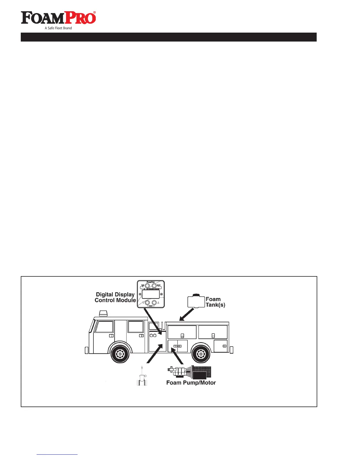
Because of the potential differences in apparatus
plumbing and foam system configuration, it is not
practical to depict exactly how each FoamPro unit can
best be installed onto a particular apparatus. Figure
2 shows the relative location of the FoamPro system
components. Most of the information contained in the
following sections, however, will apply to any situation.
It is recommended that you read the following
sections thoroughly before beginning installation of
the FoamPro system. It is also recommended that
you spend time planning and designing where and
how you intend to install this unit in the apparatus
before beginning the actual installation.
Determine the locations of the components to
be installed such as; foam tank(s), foam pump and
flowmeters. Try to place components in locations that
require the least amount of hoses and fittings.
Locate the foam pump unit in an area that is protected from
road debris and excessive heat buildup. Since the power
switch and CAL/INJECT valve are located on this unit, the
foam pump unit should be installed in an accessible area
located in the vicinity of the operator's panel.
Figure 2. System Component Location
The foam pump unit should be located below the
discharge of the foam tank(s) to provide for gravity feed
to the foam pump. The 2002 and 2024 systems can
be positioned with a suction lift not to exceed 6 ft (1.8
meters) and may be positioned accordingly. Locate the
foam tank(s) where the refilling can be done with 5 gallon
(19 liter) containers and other methods suitable to the
end user. Most water tank manufacturers will build the
foam tank(s) into the booster tank. When specifying
integral foam tank(s), make provisions for installing the
low-level sensor as well as foam suction connections
and tank drainage.
Determine a location for the Digital Display Control
Module on the operator panel of the apparatus.
Consider the routing path for the control cables from the
Digital Display Control Module to the foam pump unit
and flowmeter(s). If necessary, order longer or shorter
cable assemblies to suit the location demands.
CAUTION: Never attempt to cut or lengthen the
molded cables.
5 Installation Planning
HYPRO
Flowmeter