5
Installation and Operation Manual
System 2000
Installation and Operation Manual
System 2000
1
2
4
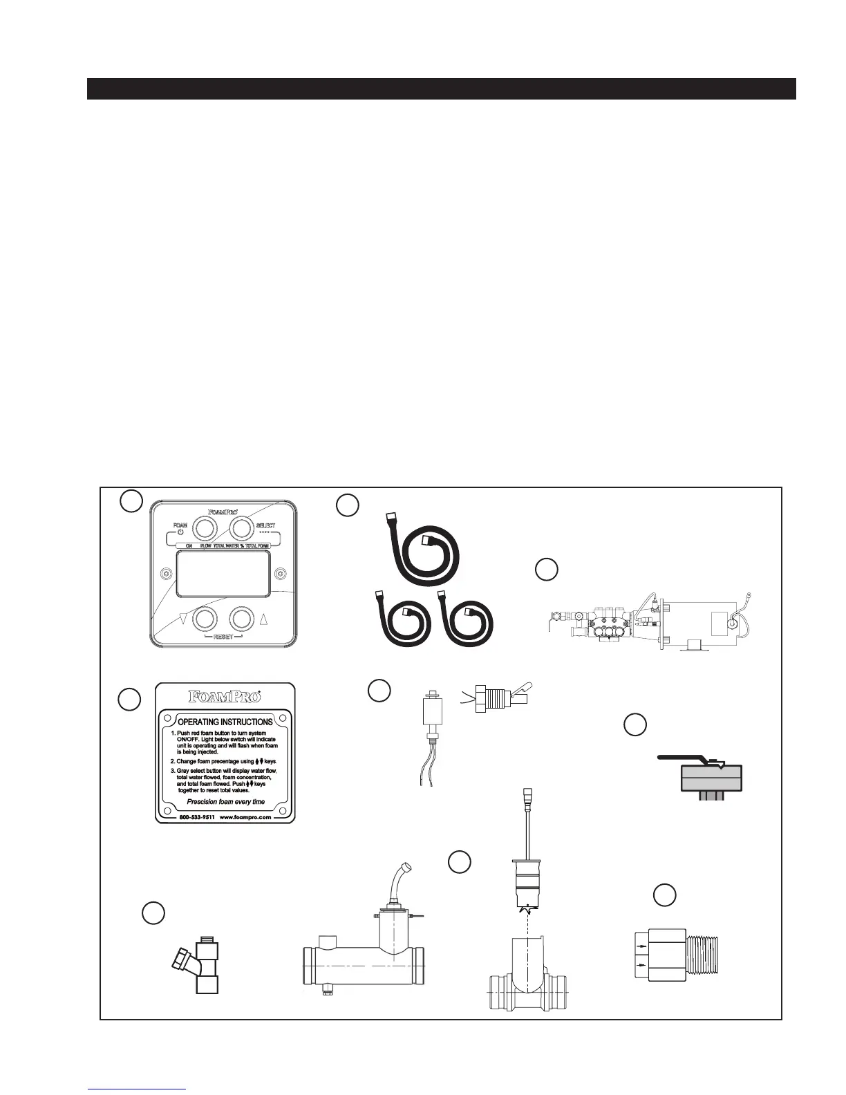
STANDARD FOAMPRO 2000 SYSTEM EQUIPMENT
The following components are packaged with the
FoamPro 2000 series:
1. Digital Display Control Module
2. Molded Cables
3. Foam Pump Assembly
4. Instruction Plate
5. Tank Low-Level Sensor (One required.
Not packaged with the unit. Order separately.)
6. Calibrate/Inject Valve with Bushing (Attached to the
pump outlet connection.)
7. Inlet Line Strainer with Nipple
8. FoamPro Paddlewheel Flowmeter or Manifold
(The flowmeter is a required component and must
be ordered separately. When ordering the 2000
series, specify the flowmeter size based on end
use requirements. The flowmeters are available
with 1-1/2 NPT x 1” Bore, 1-1/2, 2, 2-1/2, 3 and
4-inch NPT threads; or manifolds with Victaulic-
grooved ends in 1-1/2, 2, 2-1/2, 3 and 4-inch
pipe sizes. (Part numbers and flow ranges for the
various flowmeters can be found on Page 39.)
9. 1/2 Inch NPT Foam Injection Check Valve. This
NFPA required check valve prevents water back
flowing into foam systems.
6
3
9
5
Vertical Mount
(P/N 2510-0028)
Side Mount
(P/N 2510-0032)
7
3 System Component Description
8