9
Installation and Operation Manual
System 2000
Installation and Operation Manual
System 2000
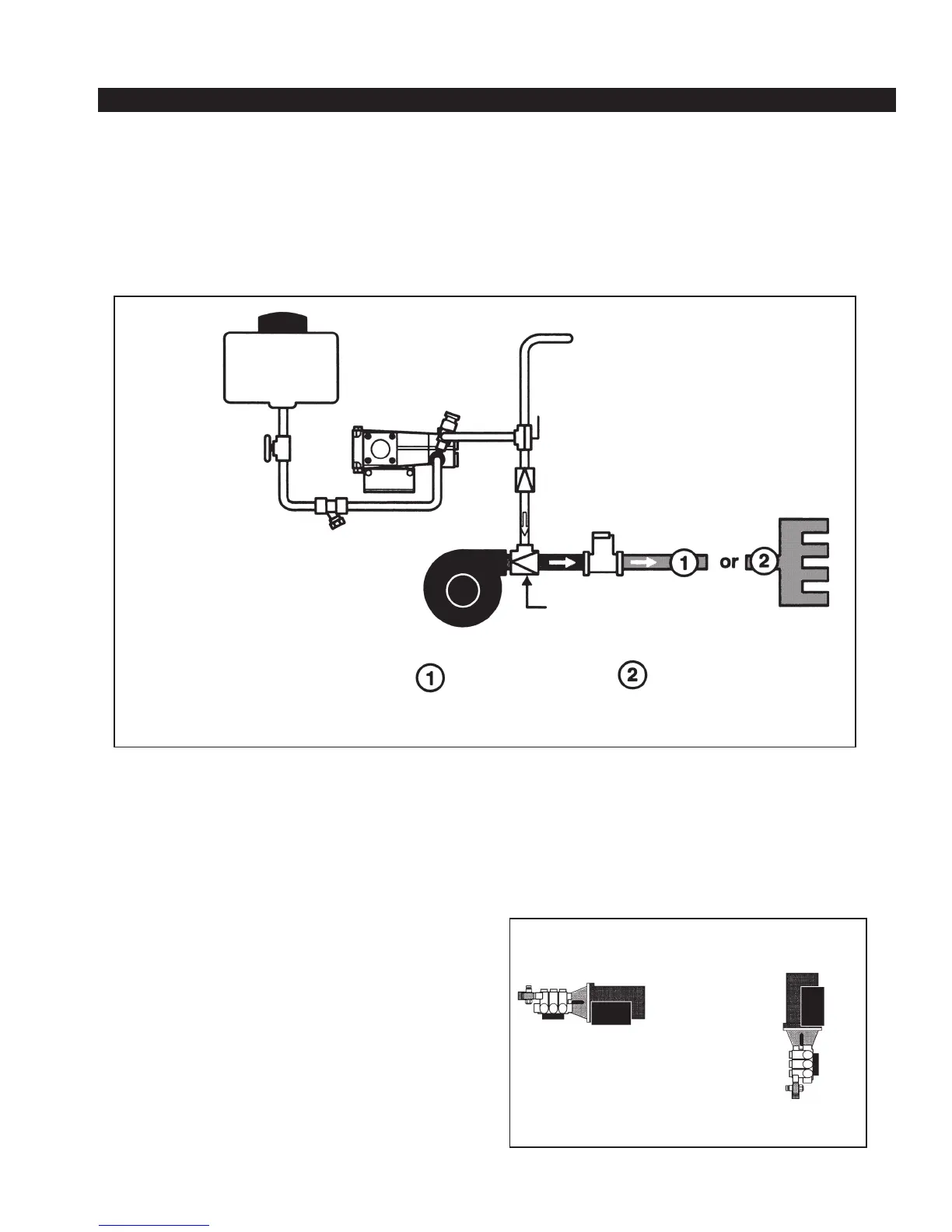
The following diagram (Figure 3) provides recommended guidelines for the location of the system components
that handle water, foam concentrate and foam solution. Note that additional options such as dual tank
systems, multiple flowmeters, etc., are covered by individual manuals included with those systems; consider
potential interferences.
A. FOAM PUMP/MOTOR BASE ASSEMBLY
The foam pump/motor base assembly must be mounted
in a horizontal position (See Figure 5). The base of the
foam pump must be anchored to a surface or structure that
is rigid and of adequate strength to withstand the vibration
and stresses of apparatus operation. Figure 4 provides the
mounting dimensions for the FoamPro 2000 series foam
pump/motor base assembly. It is required to use flexible
hose when making the hose connections to the FoamPro
2000 series. DO NOT hard pipe the system.
Position the foam pump so the circuit breaker/on-off switch
is easily accessible. Also, consider access requirements
for checking and changing the oil in the crankcase of the
foam pump. Be sure the foam concentrate hoses can be
properly routed to the inlets and outlets on the foam pump.
Position the 2001 and 2002HP foam pump assembly
so that the foam pump inlet is gravity fed from the foam
tank(s). The 2002 and 2024 foam pump assemblies can
be mounted in a position with a gravity fed inlet or with a
maximum vertical lift of no more than 6 feet (1.8 meters).
Ensure in all cases that the suction line size is appropriate
and minimal in length. Keep the usage of elbows to a
minimum and refrain from coiling or looping flexible lines.
All connections must be air tight. The foam pump/motor
base assembly must be mounted in an area to avoid
excessive exhaust system heat buildup.
6 Plumbing Component Installation
Horizontal
Mounting
Vertical
Mounting
DO DON’T
Figure 5. Foam Pump Mounting Position
Figure 3. FoamPro 2000 Series System Piping
Foam Tank
Shut-Off Valve
(Elec. or Man.)
Foam
Pump
Relief
Valve
Line
Strainer
To Calibration Container
Cal/Inject
Valve
Check Valve
Check Valve/
Foam Injection Port
Water
Pump
Single Discharge
Manifold Discharge
Flowmeter