10
Installation and Operation ManualInstallation and Operation Manual
Protect the hoses and wiring from chafing and abrasion
during operation of the foam system.
Protect the foam pump base unit from excessive road
spray and debris. Although the system is sealed and
designed to be resistant to the harsh environment of
fire fighting apparatus, a protected location with easy
operator access is the ideal installation location.
After the foam pump/motor base assembly is mounted,
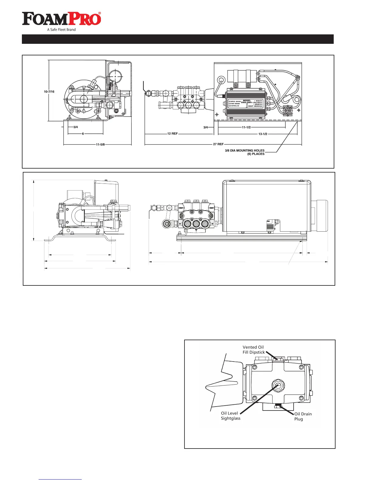
remove the shipping plug in the oil fill hole on the foam
pump gear case and replace it with the vented oil
dipstick (see Figure 6). Check the oil level by removing
the vented dipstick; make sure the oil level is to the full
mark on the dipstick. Proper oil level is also indicated
when the oil is visible in 1/2 to 3/4 of the oil level
sightglass. Add Dextron ATF oil if required. Replace
the dipstick when the oil level is correct.
Figure 6. FoamPro 2000 Series
Foam Pump Oil Level Check
Figure 4. FoamPro 2001/2002 Mounting Dimensions
B. DISCHARGE RELIEF VALVE
The discharge relief valve is installed on the outlet port
of the foam concentrate pump. It is provided to protect
the foam pump from excessive pressures. The relief
valve is factory set at 400 psi [28 BAR] (600 psi [41
BAR] for 2002HP model).
Figure 4a. FoamPro 2024 Mounting Dimensions
11-3/8"
11-7/8"
13-3/8"
22-3/4"
13/32" Mounting
Holes (4)
13/16"
33-9/16"
6-1/16"
16-1/8"
 Loading...