11
Installation and Operation Manual
System 2000
Installation and Operation Manual
System 2000
C. CAL/INJECT VALVE
The CAL/INJECT valve is mounted on the discharge side
of the foam proportioner. This valve shall be accessible by
the pump operator during normal operations. The valve is
a 3-way directional valve that selects where the output of
the foam pump will go.
Check to make sure the valve is installed properly.
Look at the ports as you move the handle, the flow should
go from the center port to each of the other ports.
The hose and fittings from the INJECT port to the
foam injector fitting should have 1/2-inch [13 mm]
inside diameter and be rated at 400 psi [28 BAR] for
2001/2002/2024 models or 600 psi [41 BAR] for 2002HP
models minimum working pressure or maximum
discharge pressure of the fire pump.
The hose from the CAL/FLUSH port may have a lower
pressure rating since it is plumbed to the atmosphere
and will not receive high pressures. This hose is used for
calibrating the foam pump, pumping the concentrate into
a container to empty the tank or to assist in priming of the
foam pump. The hose from the CAL/FLUSH port must be
long enough to reach a container outside the truck. This
hose must be coiled for storage when not in use.
D. LINE STRAINER
The line strainer that is provided with the FoamPro unit
has 3/4-inch NPT female threaded ports for the 2001 &
2002 systems and 1-inch NPT female threaded ports for
the 2024 system; and is to be installed on the inlet port
side of the foam pump. The hose from the foam tank
should have adequate wall stiffness to withstand the
vacuum of the foam pump while it is operating (23 in.
[584 mm] Hg and 50 psi [3 BAR]).
NOTE: If a pressurized water flush from one of the
discharges is incorporated, the plumbing and line
strainer exposed to this pressure must be rated
at or above the operating pressure of all other
discharge plumbing components. (400 psi [28 BAR]
minimum) (600 psi [41 BAR] for 2002HP models).
E. FLOWMETER(S)
The FoamPro 2000 Series systems are designed to
accept flow reading signals from the FoamPro
paddlewheel style flowmeter.
Proper flowmeter sizing is critical to system accuracy.
Select a flowmeter size based on actual flows required,
not standard pipe sizes. Refer to the installation drawing
at the end of this manual (Page 39) for proper flowmeter
sizing.
The flowmeters require that the amount of turbulence in
the pipe being monitored is as low as possible. Excessive
turbulence produces unstable and inaccurate flow
readings. The following installation guidelines will help
attain the best readings and maintain accuracy of the
FoamPro system when using the FoamPro paddlewheel
flowmeter in a tee or in the FoamPro manifold.
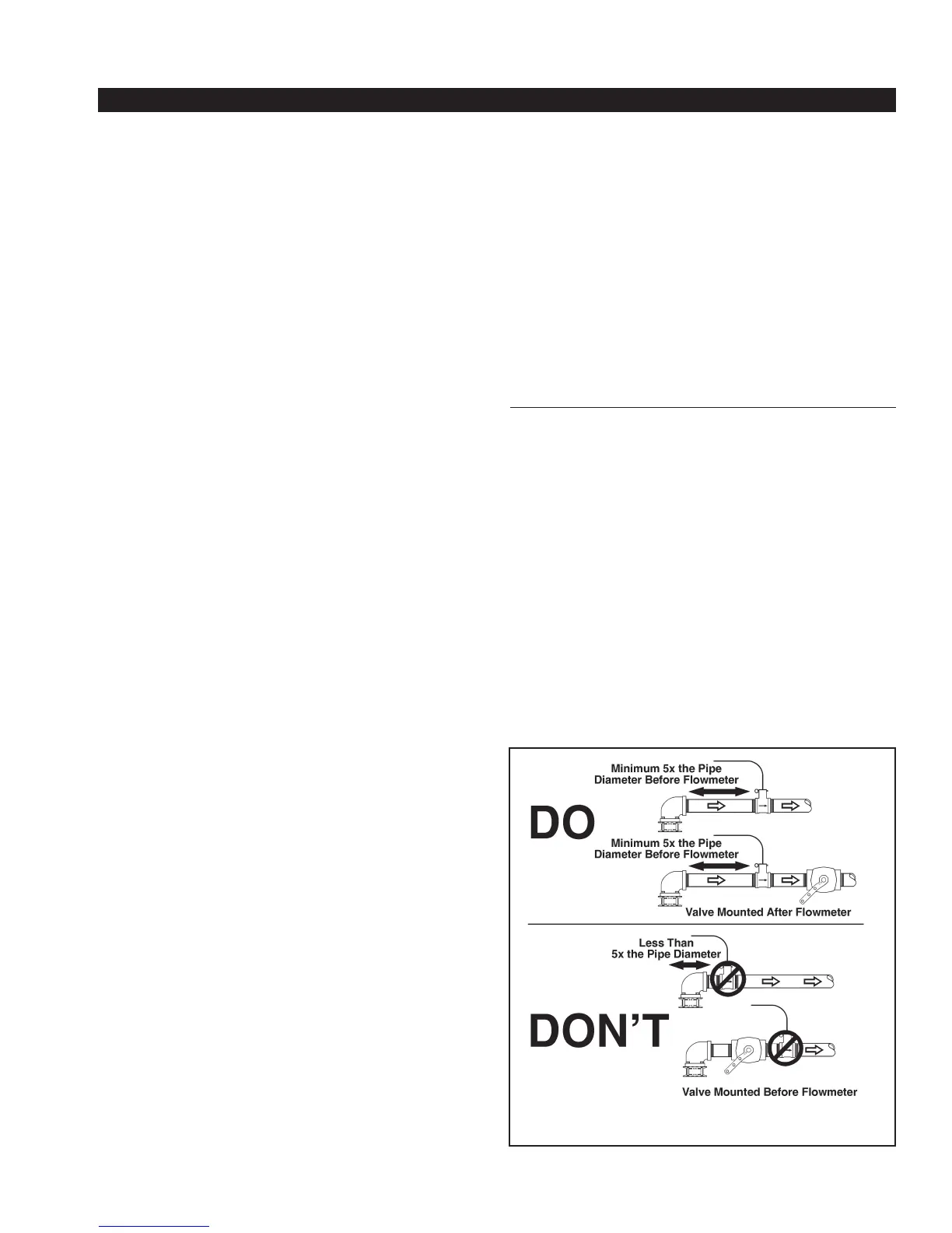
a. A minimum 5 times the pipe diameter of straight run
pipe without any fittings is necessary upstream of the
flowmeter.
10 times is better — the longer the straight run, the
lower the turbulence. Here are some examples of
required straight run:
Pipe Recommended
Size Straight Run Pipe
1-1/2 in. [38 mm] .......7-1/2 to 15 in. [191 to 381 mm]
2 in. [50 mm] .............10 to 20 in. [254 to 508 mm]
2-1/2 in. [64 mm] .......12-1/2 to 25 in. [317 to 635 mm]
3 in. [76 mm] .............15 to 30 in. [381 to 762 mm]
4 in. [100 mm] ...........20 to 40 in. [511 to 1016 mm]
b. The downstream plumbing of the flowmeter is not as
critical; but again, straight runs without fittings help
maintain accurate flow readings.
c. Do not mount a flowmeter directly after an elbow or
valve. Valves create severe turbulence when they are
“gated-down”.
d. Try to mount the flowmeters in a position that is
accessible for routine inspection and maintenance.
Figure 7. Flowmeter Placement
 Loading...