15
Installation and Operation Manual
System 2000
Installation and Operation Manual
System 2000
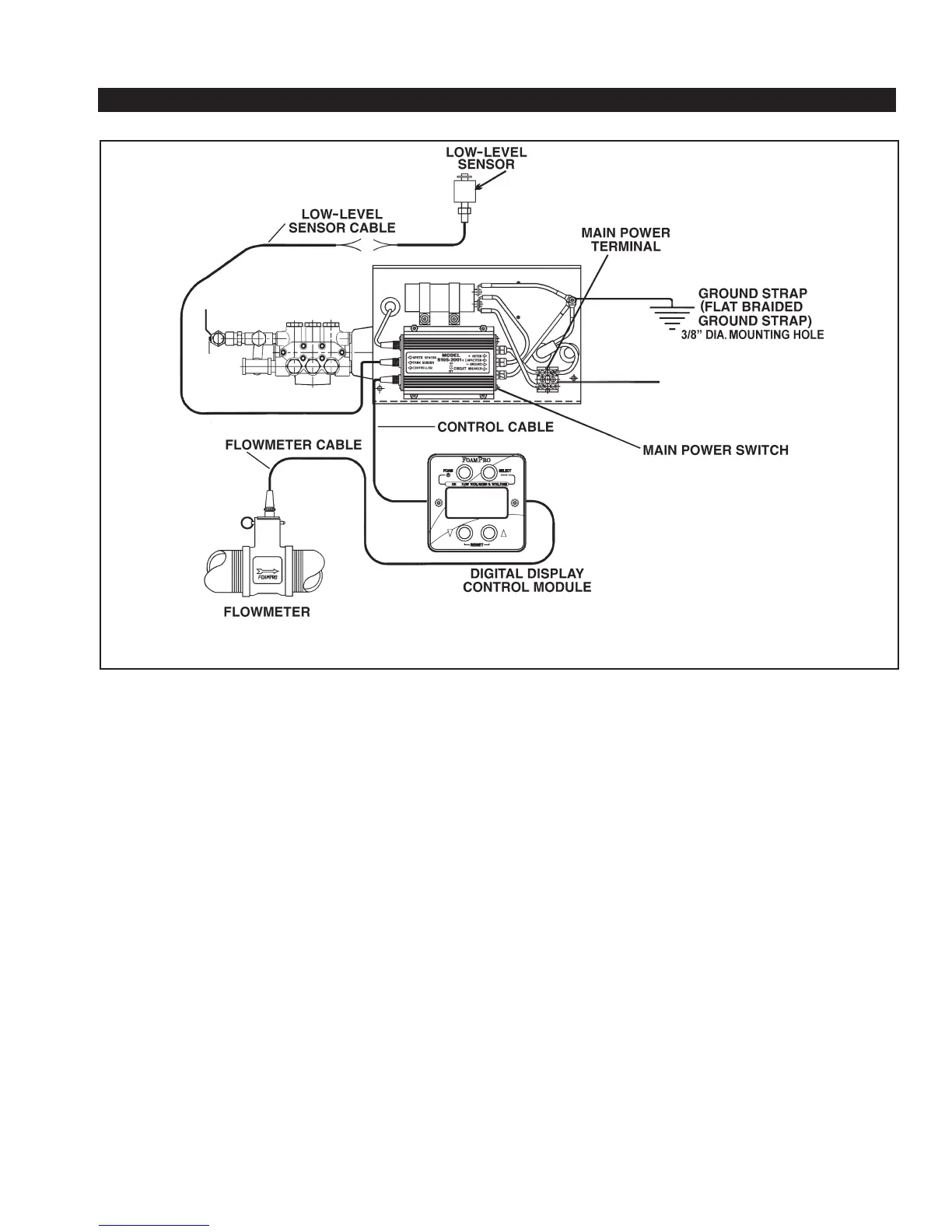
Figure 14. FoamPro 2001 Electrical Wiring Diagram
Bent pins caused by improper hookup can
prevent proper operation even when cables are
reattached properly.
• Before connecting the molded cables, inspect the
yellow seal washer in the female connector. If the
seal washer is missing or damaged, water can
enter the connector and cause corrosion of the pins
and terminals that will cause system failure.
• CAUTION: The cables shipped with each
FoamPro unit are tested at the factory with
that unit. Improper handling and forcing
connections can damage these cables, which
could result in other system damage.
• CAUTION: Always disconnect the ground
straps and control cables from the Digital
Display Control Module or other FoamPro
equipment before electric arc welding at any
point on the apparatus. Failure to do so will
result in a power surge through the unit that
could cause irreparable damage to the display
or other system components.
A. DIGITAL DISPLAY/CONTROL MODULE
The Digital Display Control Module is designed to be
mounted in the operator panel of the apparatus. The
cutout that will be needed in the operator panel is a
3-7/8 inch [98 mm] diameter hole (the same as a 3-1/2
inch [89 mm] pressure gauge). The display is secured
with four #10 socket head screws in the four holes
in the face (See Page 38 for a mounting template).
The display requires 5 inches [127 mm] minimum
from the back of the operator panel to clear wires
and connectors. Make sure there is enough clearance
behind the operator’s panel for the cables.
Once the Digital Display Control Module is mounted,
connect the control cable (red coded cable end) from
the motor driver box terminal to the 5 pin connector
on the back of the Digital Display Control Module (See
Figure 15). A color-coded decal on the motor driver
box identifies each cable connection (See Figure 16).
TO POSITIVE BATTERY CONNECTION,
BATTERY SWITCH RELAY,
OR CONTACTOR