16
Installation and Operation ManualInstallation and Operation Manual
Figure 16. Motor Driver Box Connections
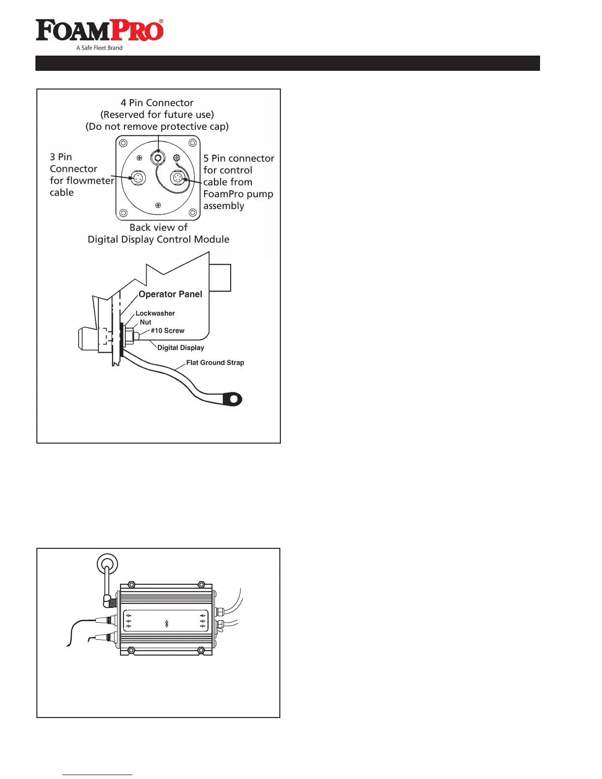
Figure 15. Digital Display Control Module Cable
Connections and Grounding
SPEED SENSOR
TANK SENSOR
CONTROLLER
CAPACITOR
DIODE
CIRCUIT BREAKER
ON
OFF
+
+
* Connections to be made
during installation.
*
*
NOTE: Make sure the panel where the Digital Display
Control Module is mounted has an adequate ground.
For stainless steel and vinyl-coated panels, a flat
ground strap must be attached from one of the four
screws holding the Digital Display Control Module
in place, to the frame of the fire truck to ensure
adequate grounding (See Figure 15).
B. FLOWMETER(s) CONNECTIONS
FOAMPRO FLOWMETER
If a single FoamPro paddlewheel-type flowmeter is
to be used, a molded cable that connects from the
flowmeter to the 3 pin connector on the Digital Display
Control Module is supplied.
MULTIFLO FLOWMETER INTERFACE
MODULES
See the instructions supplied with the MultiFlo interface
for installations requiring multiple Foampro flowmeters.
Figure 17 shows the interconnection of the flowmeters
with the Digital Display Control Module.
C. FOAM TANK CONNECTIONS
The foam tank low-level sensor must be mounted into the
bottom of the foam tank to monitor low foam concentrate
level. The switch has 1/8 inch NPT threads. Mount the
sensor in the bottom of the foam tank in an upright position.
Use suitable sealant to prevent concentrate leakage.
There must be space under the tank for the cable to be
routed to the pump base assembly (See Figure 18). Be
sure not to remove the float from the shaft on the sensor
assembly. If installed in the reverse position, “LO CON”
and “NO CON” will appear on the Digital Display Control
Module, and the system will automatically shut down after
two minutes, even if there is foam in the tank.
When the bottom of the foam tank is not accessible, the
low-tank level sensor float switch can be hung from a long
nipple attached to the top of the tank. The nipple should
be rigid enough to withstand the force of sloshing foam
when the vehicle is in motion. Make sure the low-tank
level sensor does not contact the side of the foam tank
when the vehicle is in motion (See Figure 18). Since wire
connections must be made inside the nipple, a 3/8 inch
NPT nipple with 3/8 by 1/8-inch NPT reducer at the lower
end is the minimum size recommended.
CAUTION: The foam tank low-level sensor must be
utilized to protect the foam pump from dry running.
Failure to do so will void the warranty.
Connect the sensor wires to the low-tank level sensor cable
(blue-coded cable ends). The low-tank level switch sensor
cable may be shortened or lengthened (use 18-22 AWG).
It has pigtails at one end and is not polarity sensitive.
Connect the other cable end to the motor driver box on the
foam pump/motor base assembly (see Figure 16).
Check low-tank level sensor operation after installation
using a powered test light. With no foam in the tank, the