17
Installation and Operation Manual
System 2000
Installation and Operation Manual
System 2000
light should be on. If this is not the case, remove the
clip from the end of the sensor. Remove the float and
reinstall 180° out of position. Reinstall clip.
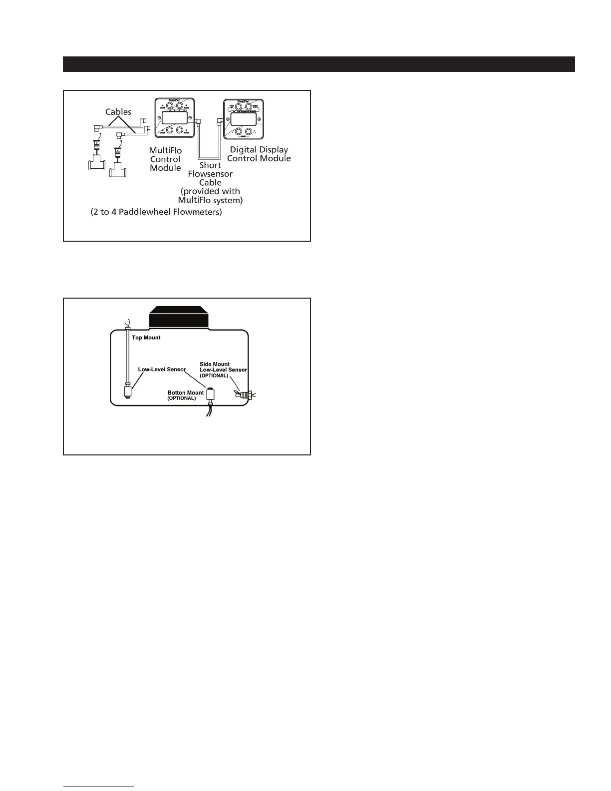
A side-mount tank level sensor is available to be used if
both the top and bottom of the tank is not accessible (See
Figure 18). The side-mount tank level sensor has 1/2-inch
NPT threads and the center of the switch must be located
approximately 2 inches [51 mm] from the bottom of the
foam tank with the float positioned on top of the switch to
move up and down.
NOTE: When the side-mount tank level sensor
senses a low concentrate condition, the system will
operate for two minutes unless the foam concentrate
level is restored. If the foam concentrate level is not
restored, the system will shut down after two minutes.
When locating the side-mount low-tank level switch on
the foam tank, sufficient foam volume must be present
for two minutes of operation. This determination will
be made using the most frequent foam concentrate
injection rate and water flow.
The side-mount tank level sensor must be sealed with
a suitable sealant to prevent concentrate leakage. After
installation, check operation of the side-mount low-tank
sensor with a powered test light. With no foam in the tank,
the light should be on. If light does not come on, rotate the
side- mount low-tank sensor until the test light is on. The
float should be allowed to swing up and down freely.
D. DC MOTOR
Provide adequate electrical power (see the
listing on Page 15) from the battery. Use 8 AWG minimum
wire directly to the battery or battery switch. Long wire runs
may require 6 AWG wire for proper operation.
See recommended wire size table on page 18.
E. ELECTRICAL POWER SUPPLY
Electrical devices can be damaged, or operate
intermittently when powered by a weak or erratic power
supply. The FoamPro 2000 Series systems are not any
different – the better the power supply, the better the
system will perform. Following the instructions that follow
will ensure the FoamPro system will perform at its best.
Power and ground connections must come directly from
the battery to the connections shown in figures 13 and 14.
These connections must come directly from the battery
without any connections to other high power devices such
as primer pumps, hose reels, auxiliary starters, light bars,
etc., with its own disconnect switch, solid state contactor
or a switch or contactor actuated by the master disconnect
switch, PTO switch, or other device. Ensure the switching
device is rated for at least twice the maximum amperage of
the system being installed.
See the Electrical Power Supply Schematic and
Recommended System Fuze Size table on page 18.
CAUTION: Connecting other high power devices to the
power or ground supply with the FoamPro system will
cause component damage.
The system maximum amperage draw is listed as follows
and must be protected with a fuse or breaker of minimum
size listed in the main power line to the system and
provides enough power and protection for the display,
driver, motor, and associated components. If attaching
other FoamPro products to the supply line, the fuse or
breaker must be sized accordingly. It is also recommended
to install a fuse or breaker of at least 50% of the main fuse
or breaker value on the main ground line. All component
power and ground connections must be common for all
FoamPro components.
• Always connect the primary 12 or 24 VDC positive lead
for the system directly to the battery or power switch using
appropriate AWG wire that is chemical resistant and pro-
tected with a wire loom. Install the proper fuse or breaker
size in the line that supplies the main power to the system.
Figure 17. MultiFlo and Flowmeter Connections
Figure 18. Foam Tank Low-Level Sensor
Mounting Options