18
Installation and Operation Manual
Recommended System Fuse Sizes
System
Model
Operating
Voltage
Maximum System
Amp Draw
Minimum Fuse or
Breaker Size
2001
12 VDC
24 VDC
41
22
45
25
2002 &
2002HP
12 VDC
24 VDC
60
30
60
30
2024 24 VDC 60 60
Recommended Wire AWG
System
Model
System
Voltage
Max
Amps
10 ft. 15 ft. 20 ft. 25 ft. 30 ft.
2001
12 VDC
24 VDC
41
22
8
8
6
8
4
8
4
6
2
6
2002 &
2002HP
12 VDC
24 VDC
60
30
6
8
4
8
4
6
2
4
2
4
2024 24 VDC 60 6 4 4 2 2
• It is recommended to connect the ground lead for
the main system directly back to the battery using the
same AWG size as the main power line and it should
also be chemical resistant wire protected in a wire
loom. Installation of a fuse or breaker of at minimum of
50% of the main power breaker in line with the ground
to the system.
• Never connect the main power or ground leads to other
leads that are connected to high power components
such as primer pumps, hose reels, auxiliary starters, etc.
• Always make the connection to the primary power
supply the last step.
• Always ensure the connections are sound and tight to
avoid erratic or poor power and ground connections to
the components.
• Always make sure the Control Display and the Base
System are grounded to the chassis using at ground
straps to reduce potential RFI and EMI issues.
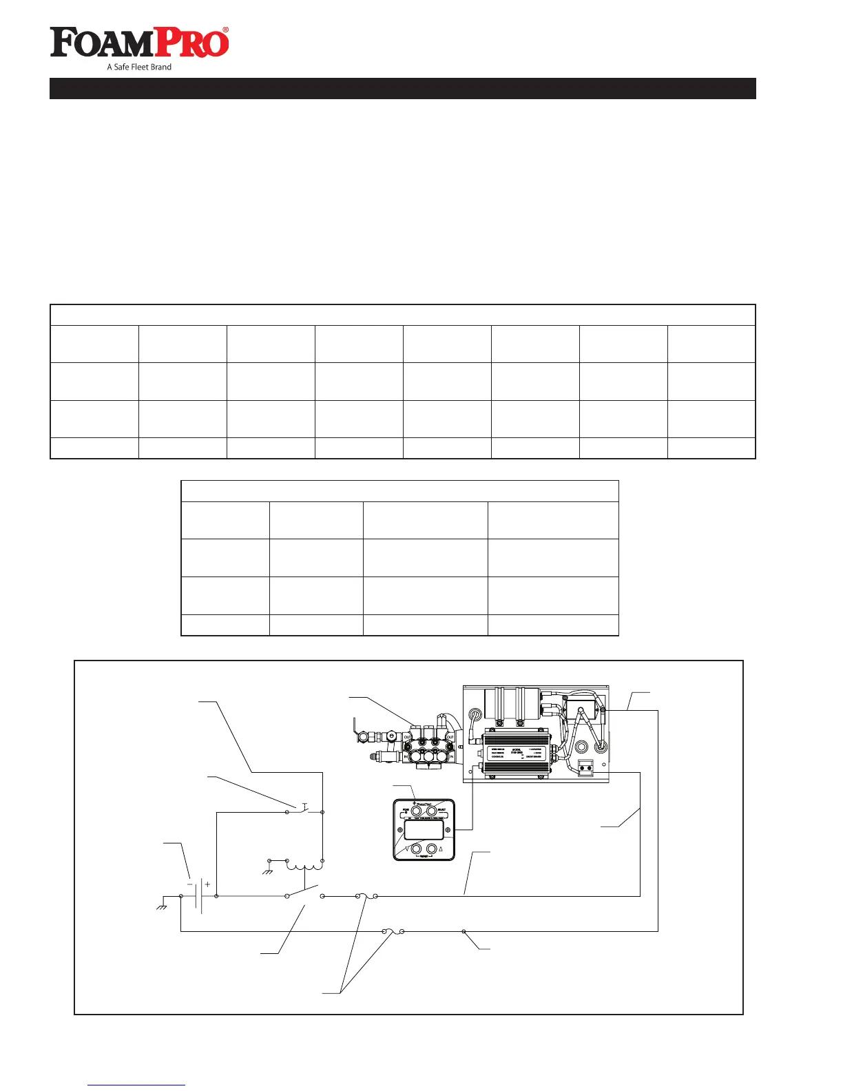
Master Disconnect Switch,
PTO Switch,
or Manual Switch
To Other Devices
Battery
Relay, or Solid
State Contactor
Appropriately Sized
Common Power Connection
for other FoamPro Accessories
Common Ground Connection
for other FoamPro Accessories
Power Lead (+)
System Z
Bracket Assy
Controller
Electrical Power Supply Schematic