907-0601-00 Rev. C Model 907 Video/Data Multiplexer – User’s Guide
Focal Technologies Corp. Page 3-6
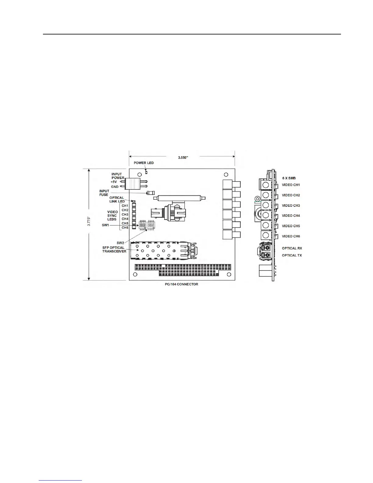
3.2.1 Remote 907V Multiplexer Card (907V-R)
Figure 3-7 shows top and side views of the 907V-R remote multiplexer card. The backplane PC/104
connector allows stacking of other PC/104 form-factor cards. A standard two-pin Molex power connector is
used for a +5 VDC power input, which includes a fuse and protection from reverse polarity and overvoltage.
Typical current draw is 0.7 A from a +5 VDC supply.
An array of diagnostic LEDs indicate board status. The Video Sync LEDs are green when proper video sync
is detected and red or orange when the input voltage is out of range, i.e. exceeds 1.5 Vpp. The Optical Link
LED is on when the card is receiving sufficient optical power and valid frames from the console. The Power
LED is on when the input power voltage is above 4 V.
Figure 3-7: 907V-R & 907V-C Multiplexer Card
All six SMB video connectors have a 75-ohm input impedance, AC-coupled. The input video signals are
streamed to the output video connectors of the 907V-C card via the optical link.
3.2.2 Console 907V Multiplexer Card (907V-C)
The card views for the 907V-C multiplexer card are identical to the 907V-R shown in Figure 3-7. The console
card electrical interfaces, optical interfaces, and switch configurations are all identical to the remote except at
the video connectors, which are outputs on the console and inputs on the remote. Output impedance for each
video connector is 75 ohms, AC-coupled.
A 907-DIAG-E diagnostic card may be stacked with the 907V-C to obtain critical system diagnostics of both
the remote and console stacks through an Ethernet interface. Details of the 907-DIAG-E card are provided in
the System Modules section.