907-0601-00 Rev. C Model 907 Video/Data Multiplexer – User’s Guide
Focal Technologies Corp. Page 6-4
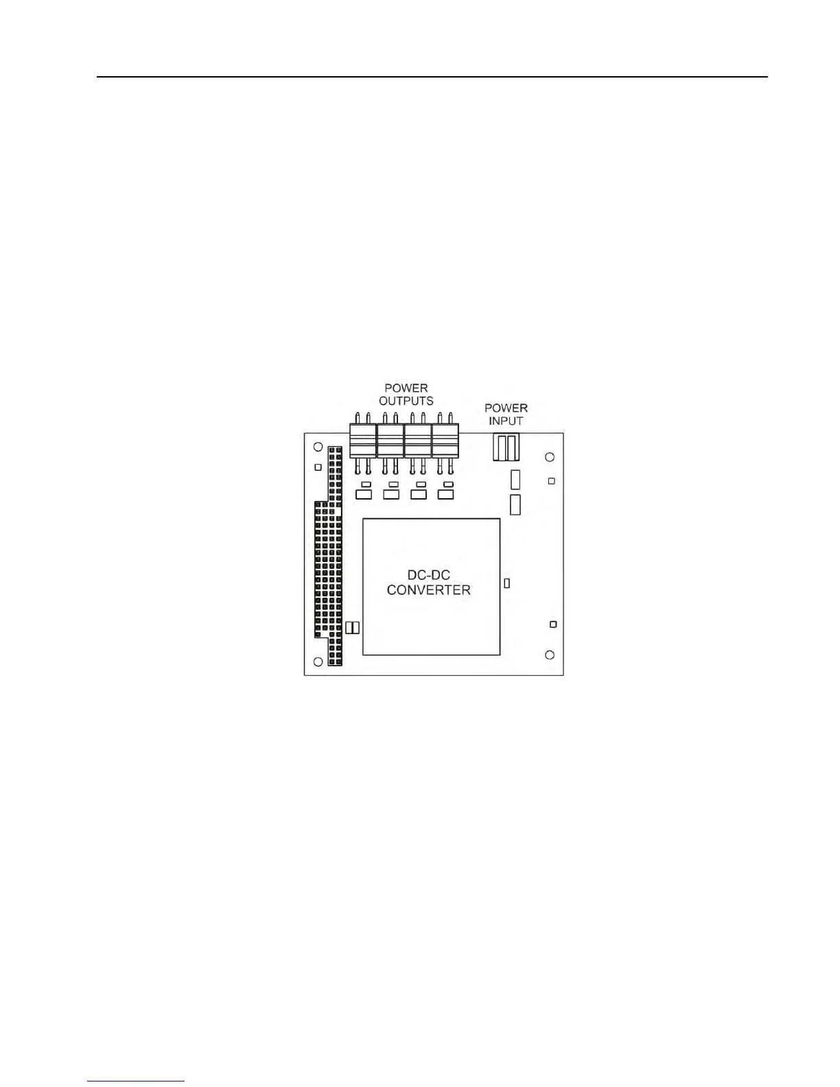
6.3 907-DC-24 (Isolated DC-DC Power Card)
The power supply card, shown below in Figure 6-4, is based on a 40 W DC-DC converter module used to
distribute power to several Model 907 cards or substacks. Power input to the DC-DC converter via a 2-pin
WAGO connector can range from 18 to 30 VDC (24 VDC nominal). Reverse protection and a 3 A replaceable
fuse are included in the power input circuit. Wire gauge for the input power harness should be 20-22 AWG
and wire gauge for the output power harness should be 18-20 AWG.
Four separate +5 VDC outputs are accessible from the 2-pin Molex connectors. Outputs are fused on the
cards to which they are connected (all 907 cards have on-board fuses). Maximum output current on any
single output connector should not exceed 4 A. The aggregate current output of the DC-DC converter should
not exceed 8 A. Typically the 907-DC-24 is mounted on the bottom of a stack or installed separately but near
the 907 stack.
Figure 6-4: 907-DC-24 Power Distribution Card
The +5V and 0V pins on each power output connector are connected to the same +5V and 0V output pins on
the DC-DC converter. These output pins on the DC-DC converter are isolated from the primary +24V nominal
input.