907-0601-00 Rev. C Model 907 Video/Data Multiplexer – User’s Guide
Focal Technologies Corp. Page 5-15
5.13 907-AIB (Dual-Socket AIB Adaptor)
The 907-AIB expansion card allows standard AIB (Adaptable Interface Board) plug-in modules from the
Model 903 systems to be employed in Model 907 stacks. Note that to accommodate the length of the plug-in
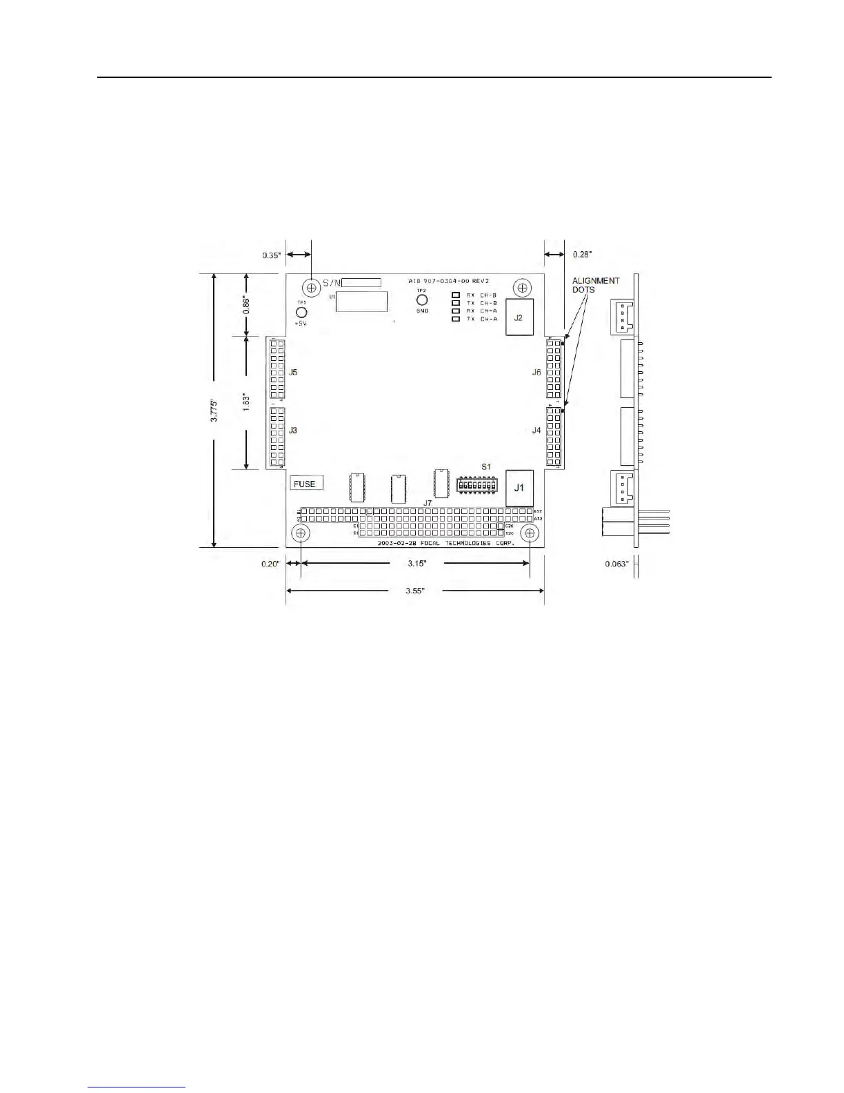
cards, the sides of the 907-AIB extend 0.28‟‟ outside the normal PC/104 form factor as shown in Figure 5-13.
Figure 5-13: 907-AIB, Adaptable Interface Board Adaptor
The 907-AIB expansion card provides two generic data channels. Two pairs of socket interfaces are
populated with AIB plug-in modules, which are accessed externally via WAGO connectors J1 and J2. A
variety of plug-in modules are available for use with the 907-AIB expansion card. The AIB plug-in modules
include analog interfaces for hydrophones and sonar (MS900) in addition to digital interfaces, such as RS-
232, RS-485/422/TTL, Tritech sonar ARCNET and CANBUS.
When installing the AIB plug-in modules into the 907-AIB expansion card, ensure the connector marked by
the white alignment dot on the module PCB is mated with the corresponding header marked with a white dot
on the 907-AIB expansion card. When removing the modules, carefully extract the plug-in board by pulling
both connectors straight out to minimize flexing of the PCB. Uninstalled AIB modules should be handled like
integrated circuits: observe ESD handling precautions and store in static dissipating bags or conductive foam.
The 907-AIB expansion card is powered from the 907 motherboard through the backplane. Actual current
draw depends on the plug-in modules installed. Switch S1 is used to configure which backplane data ports
are used for data transfer through the motherboard, per configuration drawing 907-2004-00. Defaults are data
port 1 for J3/J4 and data port 2 for J5/J6.
Refer to document 700-0271-00 for details on all of the available AIB Plug-In modules.