907-0601-00 Rev. C Model 907 Video/Data Multiplexer – User’s Guide
Focal Technologies Corp. Page iii
6.0 System Modules ................................................................................................................................... 6-1
6.1 907-EURO (Eurocard Adaptor) .................................................................................................... 6-1
6.2 907-PC104 (907 to Standard PC/104 Adaptor) ............................................................................ 6-3
6.3 907-DC-24 (Isolated DC-DC Power Card) ................................................................................... 6-4
6.4 907-CWDM (CWDM Optics Card) ................................................................................................ 6-5
6.5 907-CWDM-4 (4-Channel CWDM Optics Card) ........................................................................... 6-6
6.6 907-CWDM-8 (8-Channel CWDM Optics Card) ........................................................................... 6-7
6.7 907-FOS (1x2 SMF/MMF Fiber Optic Switch Card) ..................................................................... 6-8
6.8 907-SPLIT (1x2 Optical Splitter Card) .......................................................................................... 6-9
6.9 907-DIAG (Diagnostics Card, LED Driver) ................................................................................. 6-10
6.10 907-DIAG-E (Diagnostics Card, Ethernet) ................................................................................. 6-11
7.0 Fiber Optic System ............................................................................................................................... 7-1
7.1 Safety ............................................................................................................................................ 7-1
7.2 System Design.............................................................................................................................. 7-2
8.0 Installation and Operation ................................................................................................................... 8-1
8.1 Mounting ....................................................................................................................................... 8-1
8.2 Power ............................................................................................................................................ 8-2
8.3 Bench Test.................................................................................................................................... 8-2
8.4 Maintenance ................................................................................................................................. 8-3
8.5 Model 907 Board Handling ........................................................................................................... 8-3
Appendices
Appendix A – Fuses
Appendix B – Model 907 Cards
Appendix C – Model 907 Power Current
LIST OF TABLES
Table 3-1: 907-HDM2 Configuration Options (Defaults Shaded) .................................................................. 3-12
Table 6-1: 907 Cards Compatible with 907-DIAG-E ...................................................................................... 6-12
Table 7-1: Typical ROV System Flux Budget .................................................................................................. 7-2
LIST OF FIGURES
Figure 2-1: Example of a Model 907 Multiplexer System ................................................................................ 2-1
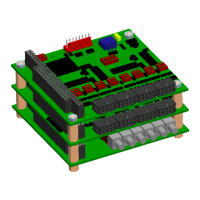
Figure 2-2: Example of a Model 907 Stack ...................................................................................................... 2-2
Figure 3-1: Remote & Console Motherboard Optical Configuration ................................................................ 3-1
Figure 3-2: Standard Model 907 Multiplexer Motherboard with WDM ............................................................. 3-2
Figure 3-3: On board I/O Channels for 907-R and 907-C Multiplexer Motherboard Cards ............................. 3-2
Figure 3-4: 907-R & 907-C Multiplexer Card ................................................................................................... 3-3
Figure 3-5: Model 907V Multiplexer Motherboard ........................................................................................... 3-5
Figure 3-6: On board I/O Channels for 907V-R and 907V-C Multiplexer Motherboard Cards ........................ 3-5
Figure 3-7: 907V-R & 907V-C Multiplexer Card............................................................................................... 3-6
Figure 3-8: Model 907Plus Multiplexer Motherboard ....................................................................................... 3-8
Figure 3-9: On board I/O Channels for 907+R and 907+C Multiplexer Motherboard Cards ........................... 3-8
Figure 3-10: 907+R Multiplexer Card ............................................................................................................... 3-9
Figure 3-11: 907+C Multiplexer Card ............................................................................................................. 3-10