20
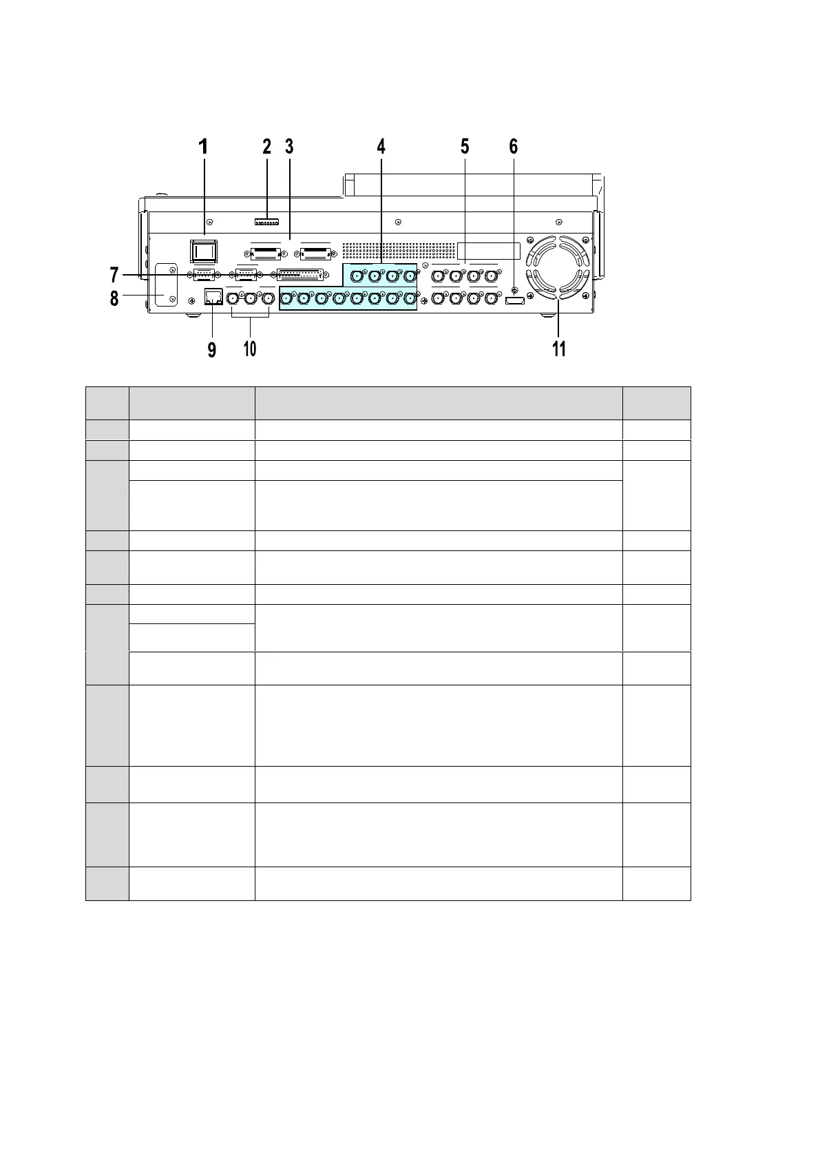
Rear Panel
Switch used to turn unit power ON / OFF.
For maintenance use. Do not change.
Supply power (12 V DC) using the supplied AC adaptor.
Optional power supply (HVS-XT110PSM) for power
redundancy.
Supply power (12 V DC) using the supplied AC adaptor.
Used to input HD/SD SDI video signal. 12 inputs (BNC)
Used to output HD/SD SDI video signal. 8 outputs
(AUX1-8) (BNC)
Used to output an HDMI output. (Type A connector)
Used to connect peripheral devices such as
HVS-30RU,VTR/VDCP devices, Routers.
(9-pin D-sub, female)
Used for GPI input/output and Tally output.
(25-pin D-sub, female)
Optional Arcnet LAN port (HVS-XT100ARC).
One port is used for HVS-AUX bus Control Box
connection.
The other port is used for loopthrough connection. It must
be 75-ohm terminated if not looped-through.
Ethernet port used for image transport and web control
100BASE-TX/1000BASE-T (RJ-45)
Used to input and output a genlock signal; tri-level sync or
black burst. (BNC)
The center terminal is used for loopthrough connection. It
must be 75-ohm terminated if not looped-through.
Used to air cool the unit to prevent overheating. Do not
block the ventilation openings.
REF OUT 1 12 3 4 5 6 7 8 2 3 4REF IN
HDMI OUT
A UX
5 6 7 8
A UX
LAN
SDI INPUT
9 10 11 12
SDI I NPUT
GPI IN/TA LLY OUT
DC12V IN
1 2
MODE SW
POWER
OFF ON
GENLOCK
RS-422
1 2