CAUTION should be observed whenever box is open to avoid damage or memory loss by static
electricity. DO NOT touch any of the circuit board, other than the intended contact noted in these
instructions. Carpets especially can build up static electricity.
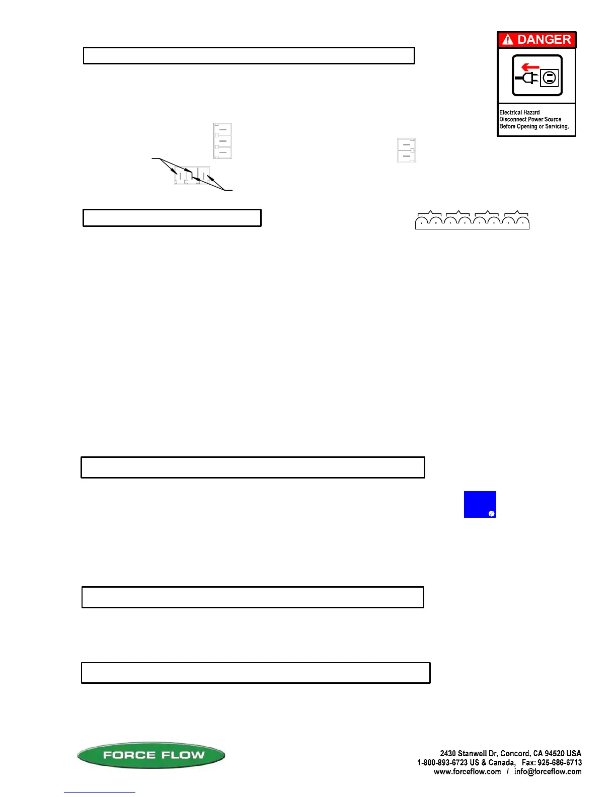
The Wizard display has been factory adjusted for standard "eye level" viewing.
If you install your indicator at a height other than eye level, you may adjust the
display angle for best viewing. Turn the blue screw potentiometer (R9 located
near the middle of the motherboard) clockwise or counter clockwise until display
appears correct at your viewing angle. The potentiometer is a 30 turn, no stop
design. A slight click will be heard when you reach min. or max. adjustment.
Be sure that indicator power circuit is sufficiently protected against transient lightning strikes
and power surges. Improper protection may void your warranty.
STATIC ELECTRICITY PROTECTION
LIGHTNING ~ SURGE PROTECTION:
6 DISPLAY VIEW ANGLE ADJUSTMENTS
5 RELAY OPTION
4 MODBUS SERIAL COMMUNICATION OPTION
QUESTIONS ? Help Hotline: 1-800-893-6723
W.12
File: T4\NEW O&M 2007\W12 WIZ NEW PR328 WZININ2A.tcw
05/23/08 MT
NO: Circuit IS complete until relay is activated. (i.e. turning OFF a pump)
RELAYS
NC: Circuit is NOT complete until the relay is activated. (i.e.turning ON a warning light).
#1
O
U
T
(
1
)
I
N
(
1
)
O
U
T
(
2
)
I
N
(
2
)
O
U
T
(
3
)
I
N
(
3
)
O
U
T
(
4
)
I
N
(
4
)
SOLID STATE relays for external apparatus (pumps, valves,
alarms, etc) may be ordered either Normally Open (NO) or
Normally Closed (NC).
SOLID STATE relays are rated at: 3amp Max. (fused @ 4amp) 1.5amp motorload.
The Wizard 4000 is provided with a separate 1/2" conduit connector for your relay wiring.
To format relays, go to SETUP MENU 12, "ALARM/RLY CONFIG".
DRY CONTACT relays (SCADA, PLC, etc) inputs may be ordered either Normally Open
(NO) or Normally Closed (NC).
DRY CONTACT relays are rated at: 0.5amp @ 12VDC maximum (fused @ 1amp).
#2
#3
#4
The Wizard 4000 is provided with a separate 1/2" conduit connector for your serial port
communication wiring. DO NOT co-locate inductive load wiring or power lines with
communication wiring. Attach your communication wiring per the following:
RS232
RS485
Data OUT line
+
_
R
G
T
R
S
4
8
5
J
1
Data IN line
Signal Ground
Positive
Negaitive
R9
Potentiometer (blue)
located near middle
of motherboard
FOR RS485 SHIFT JUMPER
TO RIGHT 2 PINS
FOR RS232
SHIFT JUMPER
TO LEFT 2 PINS
(OPTION MODEL NO's: W5ASP-OD, CD, OS, CS)
(OPTION MODEL NO's: WRS232 & WRS485)
J
4
RS232