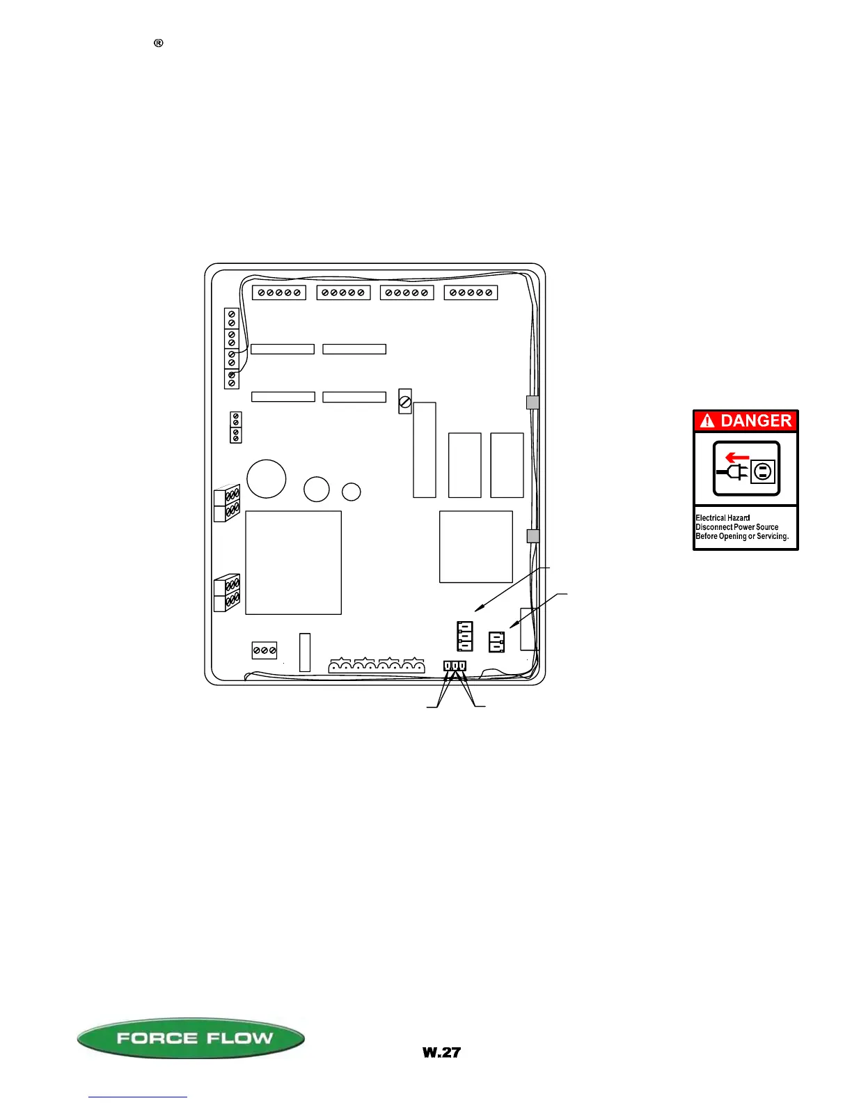
LOAD CELL/ULTRASONIC CONNECTIONS
RELAYS
#1 #2 #3 #4
DISPLAY ANGLE
ADJUSTMENT (BLUE)
E
P
R
O
M
RAM
CPU
POWER SUPPLY
POWER IN
#
1
#
2
#
3
#
4
Wizard 4000 Digital Indicator
FUSE
2430 Stanwell Dr, Concord, CA 94520 USA
1-800-893-6723 US & Canada, Fax: 925-686-6713
www.forceflow.com / info@forceflow.com
File: T4\O&M\WIZ MSTR\NEW 2007\W27 WIZ NEW MODBUS COMM.tcw
04/08/08 MT
RS232 (J1)
P
1
+
2
4
V
D
C
f
o
r
U
l
t
r
a
s
o
n
i
c
s
#1
#2
#3
#4
+
_
R
G
T
R
S
4
8
5
R
S
2
3
2
RS485 (J4)
MODBUS ASCII SERIAL COMMUNICATION
CONFIGURATION
The Wizard 4000 Digital Weight Indicator has the ability to independently monitor up to four separate
scales or sensors (four channels). The MODBUS ASCII Serial Communication option allows all of the
standard data functions to be sent to the receiving instrument via the RS232 / RS485 serial outputs.
COMMUNICATION SETUP
DATA BITS 8
STOP BIT 1
PARITY NO
BAUD RATE 9600
DEVICE ADDRESS
Device address is factory preset to "1".
To assign a different address (1-247), see CHANNEL ID (Item #2) in SETUP menu.
FOR RS232 SHIFT
JUMPER TO LEFT
2 PINS
FOR RS485 SHIFT
JUMPER TO RIGHT
2 PINS
(OPTION MODEL NO's. WRS232 & WRS485)