TURN OFF MAIN POWER BEFORE CONNECTING !! Use a dedicated 110/220 VAC (using 220 VAC requires
changing the voltage selector switch position to 220 VAC. This switch is located between the incoming power
connector and the power transformer) power line, connected directly to the main power panel at the facility. DO NOT
connect any other inductive loads, relays, etc. to this power line ! Resulting power surges can damage the
electronics !!! Use far left bottom port and connect per following: (NOTE: Use 1/2" conduit connector)
QUESTIONS ? Help Hotline: 1-800-893-6723
Your 4-20 MA signals are internally powered for up to 900 OHMS each.
DO NOT use external loop power. Run 4-20 MA wiring up the right hand
side of enclosure using the cableclamps to keep wires off of PC Board.
(NOTE: Use 1/2" conduit connector). If more than one (1) 4-20 MA
signal is used, you may use the same conduit and connector, but DO NOT
run 4-20 MA signals with any other power lines, which carry an inductive load.
+ 4-20MA LOOP
- 4-20MA LOOP
DESCRIPTION
POWER IN (110 VAC)
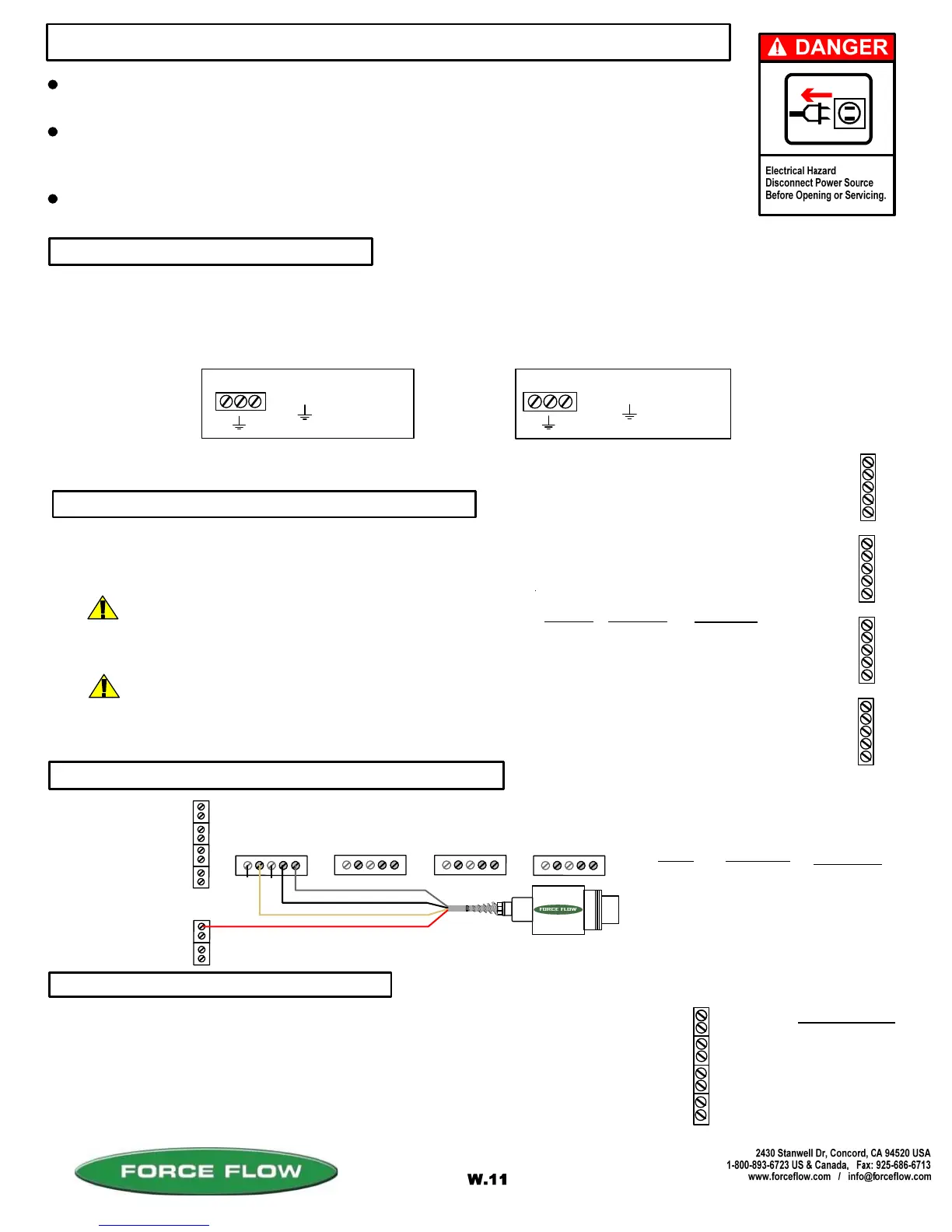
The Wizard 4000 indicator is shipped with the load cell(s) already connected. If routing load cell cable through conduit
or trimming cable length, remove cable connector from motherboard, then cable from connector and finally cable from
Wizard enclosure. After routing cable through conduit or trimming length, reverse above procedure to reconnect. A
separate cord connector is provided into the enclosure for each load cell cable.
+ EXCITATION
+ SIGNAL
- SIGNAL
- EXCITATION
SHIELD
WIRE COLOR
RED
GREEN
WHITE
BLACK
BRAIDED WIRE
PC BOARD
+ X
+ S
- S
- X
SH
+
X
4
+
S
4
-
S
4
-
X
4
S
H
+
X
3
+
S
3
-
S
3
-
X
3
S
H
+
X
2
+
S
2
-
S
2
-
X
2
S
H
+
X
1
+
S
1
-
S
1
-
X
1
S
H
S
c
a
l
e
#
4
S
c
a
l
e
#
1
S
c
a
l
e
#
2
S
c
a
l
e
#
3
DESCRIPTION
-
+
-
+
-
+
-
+
1
4
1
3
1
2
1
1
Scale #4
= HOT
= GROUND
= COMMON
3 4-20 MA SIGNALS
2 IF "LOAD CELL" CONNECTION
1 POWER HOOK-UP
+ C
File: T4\NEW O&M 2007\W11 WIZ NEW PR328 WZININST.tcw
04/08/08 MT
Scale #3
Scale #2
Scale #1
+ C
+
C
WIZARD 4000 INDICATOR INSTALLATION & WIRING
ALL CONNECTORS HAVE A "PLUG-IN" FEATURE TO ASSIST IN CONNECTING WIRES.
REMOVE THE CONNECTOR FROM THE BOARD BEFORE ATTACHING WIRES.
ALWAYS SHUT OFF MAIN POWER, AS WELL AS POWER TO ANY AUXILIARY EQUIPMENT
THAT WILL BE INSTALLED IN THIS UNIT, BEFORE OPENING FRONT OF CASE !!
INDICATOR IS NOT APPROVED FOR USE IN HAZARDOUS LOCATIONS. IF YOUR INSTALLATION
CONSTITUTES AN EXPLOSIVE OR COMBUSTIBLE ENVIRONMENT, PLEASE CONSULT FACTORY
FOR SAFETY PRECAUTIONS.
2 IF "ULTRASONIC SENSOR" CONNECTION
P
1
+X1
+
S
1
-S1
-
X
1
S
H
+X2
+
S
2
-S2
-
X
2
S
H
+X3
+
S
3
-S3
-
X
3
S
H
+X4
+
S
4
-S4
-
X
4
S
H
Scale #1 #2
#3
#4
RED (+ EXCITATION) to -V
WHITE or CLEAR to +MA
B LACK (GROUND) to - MA
SILVER or BARE (SHEID) to GRD
BOARD
P1
+SI
- X1
SH
WIRE COLOR
RED
WHITE
BLACK
SILVER
DESCRIPTION
+ EXCITATION
+ SIGNAL
GROUND
SHIELD
UNUSED
UNUSED
14
13
12
11
= HOT
= GROUND
= HOT
+
C
POWER IN (220 VAC)
OR
CHOOSE THE 2ND STEP THAT RELATES TO THE EQUIPMENT PURCHASED:
®
ROUTING CABLE IN CONDUIT
TRIMMING LOAD CELL CABLE
More than one load cell can be routed in a single
conduit. Load cells must not share conduit with
power lines or wiring from any inductive load.
Wizard 4000 is pre-calibrated at factory based on supplied cable lengths. Depending
on how much cable is trimmed, field recalibration of Wizard may be required for best
accuracy. Contact factory for more information.
(OPTION MODEL NO. WMA420)