17
Names and Functions
OUT
DATA
IN
DATA
SCSI
Display Section
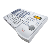
11. Data output jack [DATA OUT] (Connector: OPTICAL)
Connect this jack to the OPTICAL digital input (or adat In)
of an external digital device to save song data to a DAT or
an adat, or to record digitally to a digital device (MD, DAT,
CD-R, or adat).
Refer to page 48 for more information on using the DATA OUT
jack.
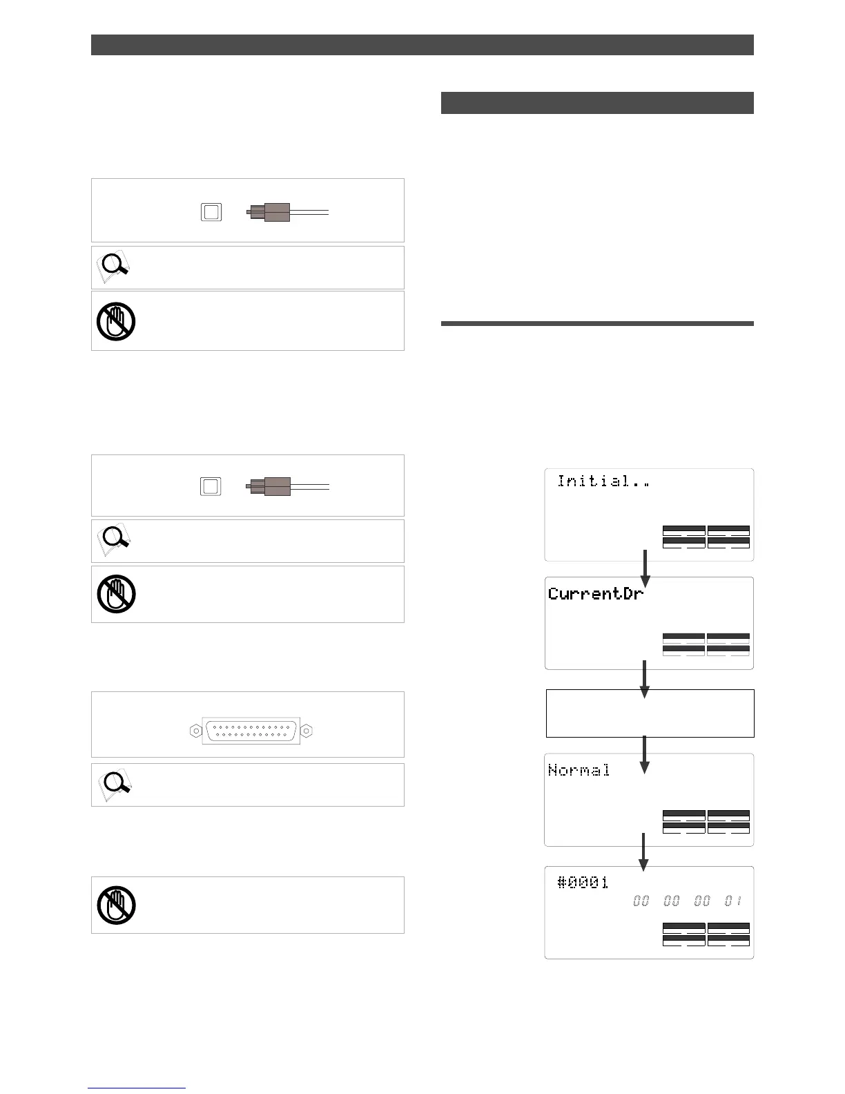
12. Data input jack [DATA IN] (Connector: OPTICAL)
Connect this jack to the OPTICAL digital output (or adat
Out) of an external digital device to load song data from a
DAT or an adat, or to record data digitally from a digital
device (MD, DAT, CD-R, or adat) to the FD-8.
Refer to page 48 for more information on using the DATA IN
jack.
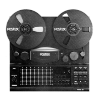
13. SCSI connector [SCSI] (Connector: D-SUB 25-pin)
Connect an external current SCSI drive as the recording
media or as a backup SCSI drive for the FD-8.
Refer to the “Quick Operation Guide” for information on
connecting an external SCSI drive.
14. AC IN connector
The power cable packaged with this recorder ia connected
here.
The FD-8 uses a liquid crystal display which integrates a 9-
digit/35-dot message section, 7-segment display section,
and level meters.
The level meters indicate the output level of tracks 1-8 and
stereo out L/R.
The time display shows various temporal information in
different units, such as ABS time (absolute time), MTC (MIDI
timecode), BAR/BEAT/CLK (bar/beat/clock), and makes it
easy to check the recorder’s current time.
The message display shows various messages required to
operate the FD-8, and offers interactive operation.
This section describes display functions along with examples.
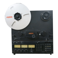
Display when the power is turned on
When you turn on the power to the FD-8 and the connected
external SCSI drive (a formatted removable disk or hard
disk), the display shows the [Initial...] message, [Current
Dr], the name of the connected current drive, then recording
mode (Master or Normal), and finally the top position of
the disk in the Time Base (ABS, MTC, or BAR/BEAT/CLK)
used in the last Program before you turned the power off.
The following example indicates that the FD-8 started with
the ABS Time Base used in Program 1.
Note:
You can save only the data recorded on the current
drive formatted in [Master] mode to a DAT or adat. You
cannot save data recorded in [Normal] mode.
Note:
You can load the data only to the current drive
formatted in [Master] mode. You cannot load data recorded
in [Normal] mode.
Indicating Time Base
ABS 0 (top of the disk)
The current drive is
recognized. (If the cur-
rent drive is a SCSI
device, [SCSI] lights
up. If the current drive
is an optional internal
hard disk, [IDE] lights
up.)
The name of the SCSI drive (The name is
different, depending on the type of device.)
Indicating a recording
mode used during for-
matting.
15. Power switch [POWER]
This switch turns power on and off to the FD-8.
Note:
Always plug the power cable to the recorder before
plugging the cable into the wall outlet.