IN-GNC03/4/5/6 - 23 - © Future Products Group
Setting Up cont.
GN SERIES REFRIGERATED WELL - INSTALLATION
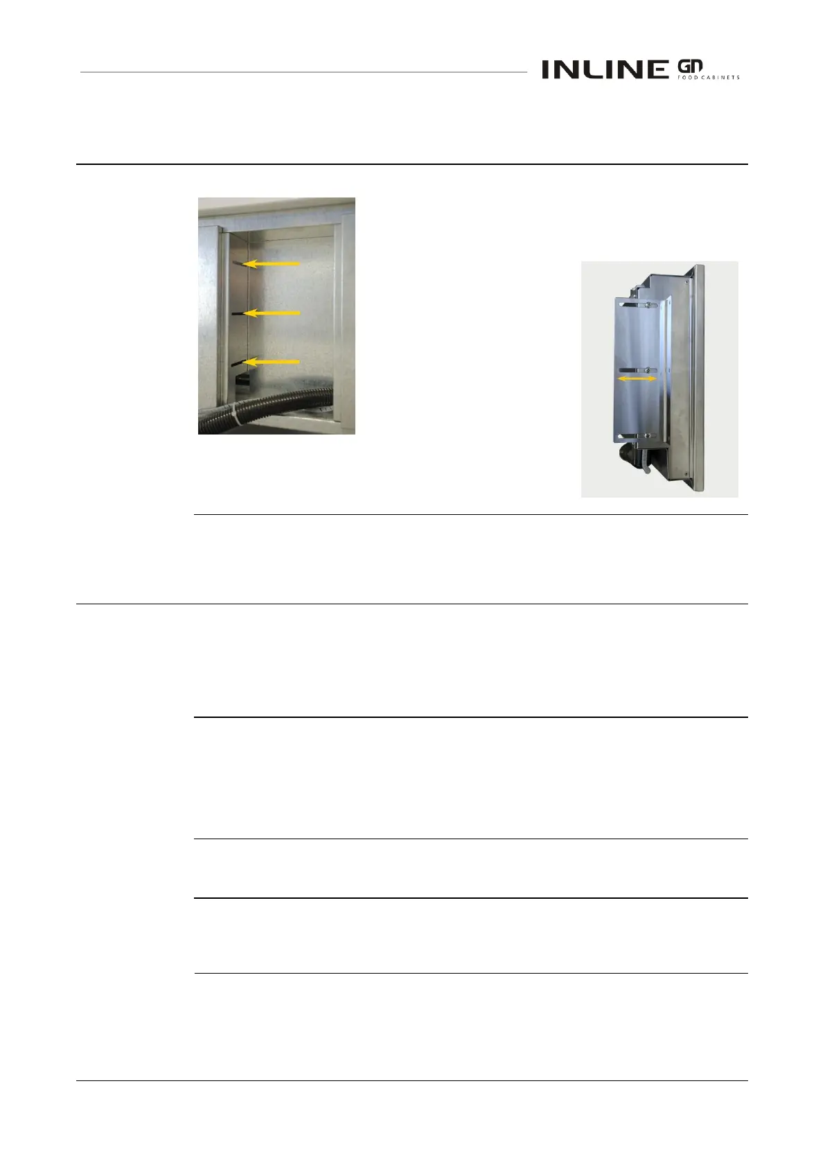
When delivered, the panel is mounted on the base
assembly.
It is secured by six screws, passing through slots in the
base chassis.
If this location is suitable,
loosen the screws and slide
the panel forward to mate with
the joinery cut-out.
If the panel is to be located
elsewhere on the joinery, use
the two slotted mounting
brackets provided.
They will be found secured to the base chassis, by the
six control panel mounting screws.
Location
GN SERIES REFRIGERATED WELL
-
INSTALLATION
The well is designed to meet the HACCP specifications with normal room air
circulation.
The well should not be placed in a location where draughts could warm the
displayed food, i.e. close to a door or air conditioning vent.
Air louvers/grills in the joinery must not be blocked.
If air flow is restricted, refrigeration efficiency will decrease and the condenser
will overheat.
If a boil-off unit is used, it is essential to ensure good ventilation.
Access to the underside of the well is required for cleaning and servicing.
Before use for the first time, operate the well for 4 hours, to remove any fumes
or odours, which may be present. This will avoid possible tainting of food.