FGR2-PE Wirelss Data Transceiver
LUM0024AB Rev A
This port is currently non-functioning. No settings and no diagnostics are delivered to this port. All
Plus-style transceivers must be programmed using Ethernet, either through the configuration Web
pages or using FreeWave Tool Suite. For more information about the setup tools available, see
"ConfigurationTool Options" on page 16.
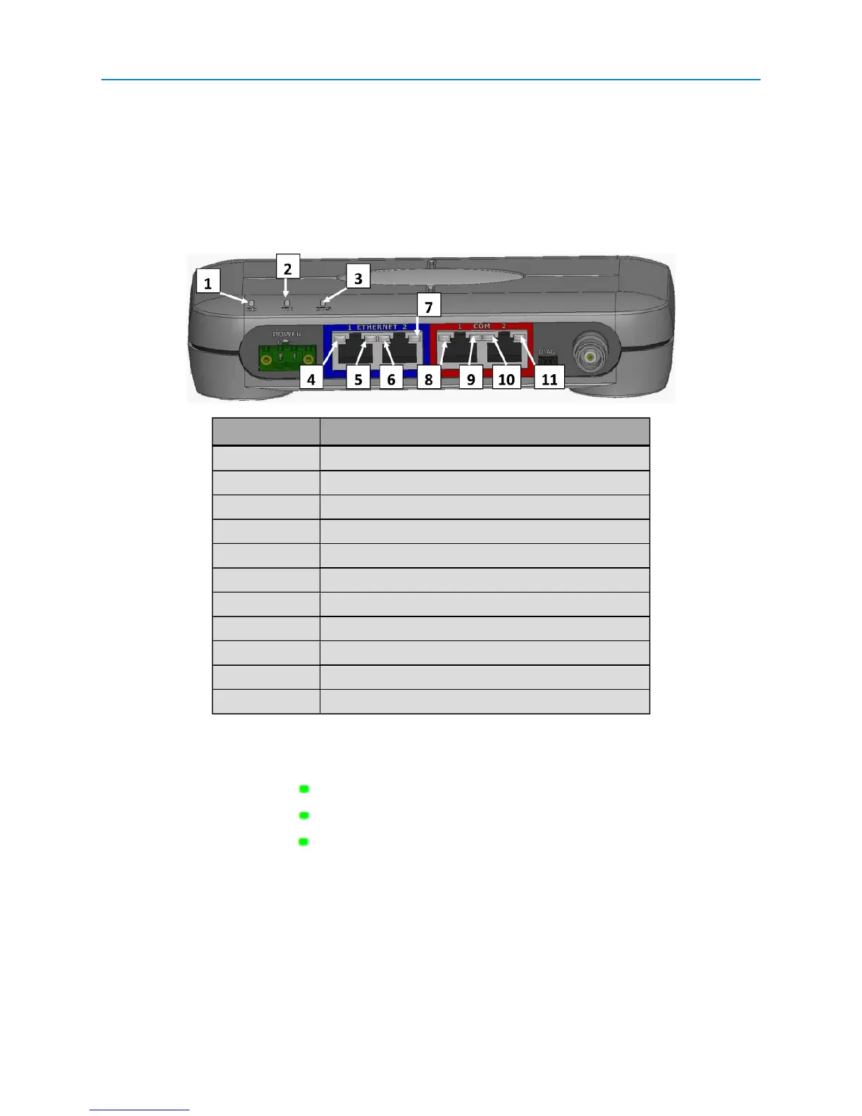
l An antenna port
In addition, the transceiver includes LEDs to help you determine when data is being received or sent from the
transceiver, as well as to provide additional information about the transceiver's state.
Label # Above Description
1 CD
2 TX
3 CTS
4 Ethernet 1 10 BaseT Link/Activity
5 Ethernet 1 100 BaseT Link
6 Ethernet 2 10 BaseT Link/Activity
7 Ethernet 2 100 BaseT Link
8 COM 1 Data (C1)
9 Error 1 (E1)
10 COM 2 Data (C2)
11 Error 2 (E2)
Boot-Up LED Sequence
The LEDs on the Ethernet transceiver follow the sequence below when the transceiver powers up:
1.
C1 lights solid green
2.
C2 lights solid green , C1 remains lit
3.
E2 lights solid green , C1 and C2 remain lit
4. C1 turns off
5. C2 turns off
6. E2 turns off
Ethernet Port Conditions
2