ICU Electronic Control Unit Acronyms
ABS Antilock Brake System ICU Instrumentation Control Unit
ACM Aftertreatment Control Module MCM Motor Control Module
CGW Central Gateway RDF Radar Front End
CPC Common Powertrain Controller SAS Steering Angle Sensor
DCMD Door Control Module, Driver sSAM Single Signal Detect and Actuation Module
DCMP Door Control Module, Passenger TCM Transmission Control Module
HVCF Heating/Ventilation/AC Front (HVAC) TPMS Tire Pressure Monitoring System
HVCP Heating/Ventilation/AC, Auxiliary (HVAC) VRDU Video Radar Decision Unit
Table 8.1, ICU Electronic Control Unit Acronyms
Power Distribution
The power distribution system provides battery power
to the electrical and electronic systems.
The following components make up the vehicle
power distribution system:
•
Battery Cable Access (BCA)
•
Power Distribution Modules (PDMe and PDMi)
•
Cab Load Disconnect Switch
Vehicle power is supplied by the batteries to the
battery cable access (BCA) box. The BCA front wall
pass-through is the primary interface through which
battery power gets transferred from outside the cab
to the inside. It is located on the passenger side of
the engine compartment front wall. This provides a
disconnect point for harness service, testing, and
replacement. See
Fig. 8.5.
The power supplied by the batteries goes to the
vehicle power distribution modules and the single
signal detect and actuation (sSAM) module.
The PDMs are fuse power distribution boxes. They
provide power and circuit protection for powertrain
needs, cab functions, and various stand alone
modules. They also supply power to the emergency
power supply circuits in the event of a module failure.
The PDMe is located in the engine compartment on
the frontwall. See
Fig. 8.6. The PDMi is located in
the vehicle electronics bay, behind the passenger-
side dash panel. See
Fig. 8.7.
Depending on a vehicle’s specifications, the fuses
and relays installed and their locations can vary.
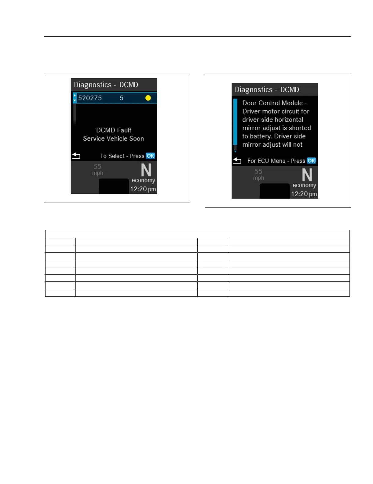
f611442a08/26/2016
Fig. 8.3, Information Screen for an Active Fault Code
f61144308/26/2016
Fig. 8.4, Additional Information for the Fault
Electrical System
8.2