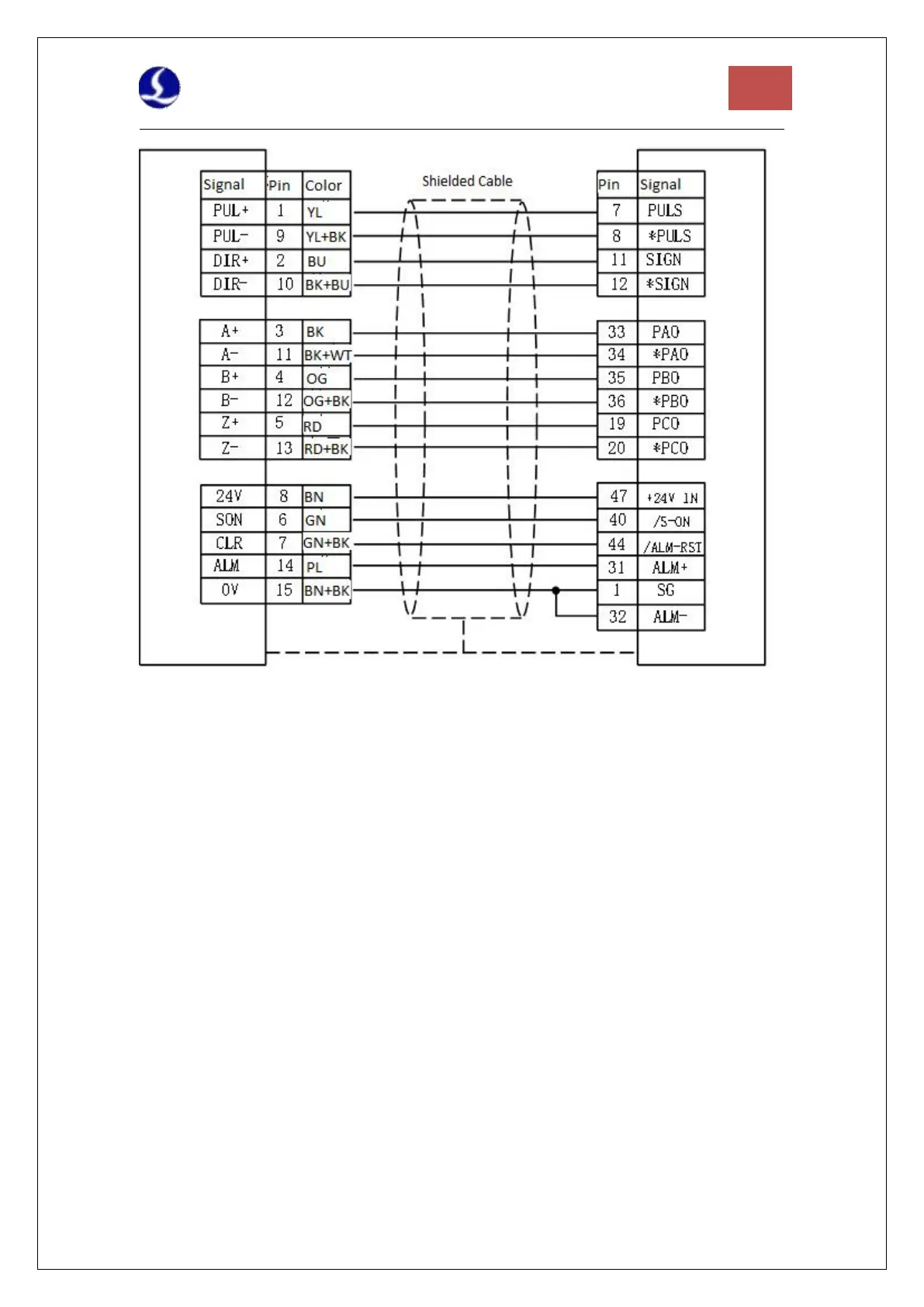
Figure 10 Yaskawa Servo Wiring Diagram
Pay attention to the following when connecting drives in other brands:
1. Please first confirm the type of SON signal of the servo drive you choose and whether it is
active low (that is, it is ON when it is connected to the GND of the 24V power supply).
2. Make sure the parameter of the servo drive: the pulse signal received is "pulse + direction".
3. Confirm whether there is an external emergency stop signal input in the input terminal of the
servo drive, and its logic.
4. Before the test run of the driver, 24V power must be supplied to the terminal board first,
because the 24V power required by the servo is transferred through the terminal board.
5. If the drive still cannot run, make sure that the parameter is set to not use "POT/NOT".