30
Knockouts on the Fronius IG Plus
General The inverter contains several knockouts of different sizes. When knocked out, the open-
ings are used for the inputs of various wires.
Knockouts on the
Fronius IG Plus
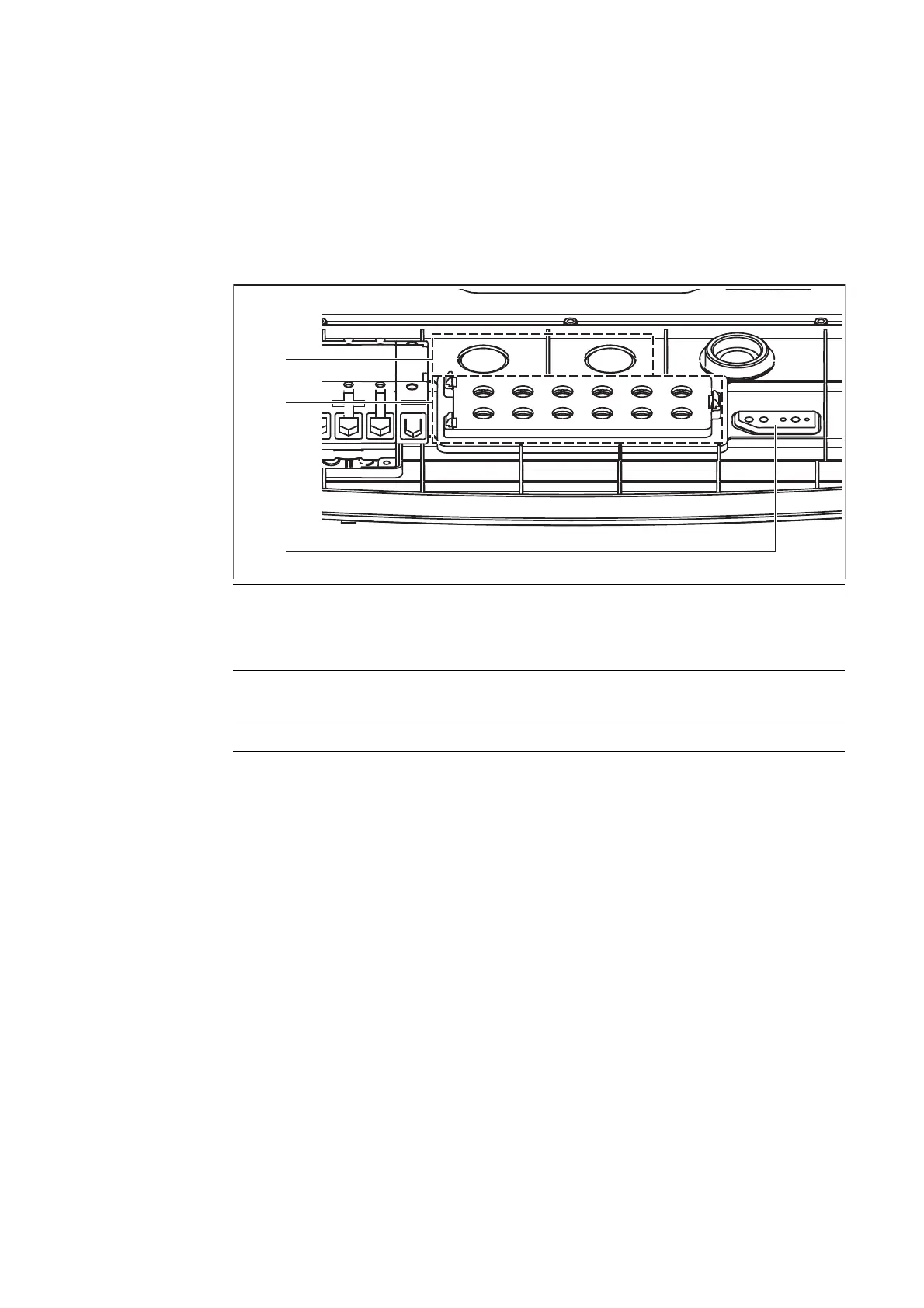
for wire inputs
Item Description
(1) 2 cable inputs for M32 metric screw joint
(for DC cables with a cross section > 16 mm²)
(2) 12 cables inputs for 6 solar module strings DC
(for a cable diameter of 5 - 9.2 mm)
(3) Sealing insert (cable input for plug-in card wire)
Removing Knock-
outs
The knockouts made from plastic as well as the larger ones made from metal should only
be removed from the outside in.
The smaller knockouts made from metal should be removed from the inside out.
You should only remove the number of knockouts required for the available cables (e.g., 6
openings for 3 module strings).
The plastic knockouts are also equipped with centering holes so that they can be drilled
out if required.