36
Maximum AC-
side overcurrent
protection
1
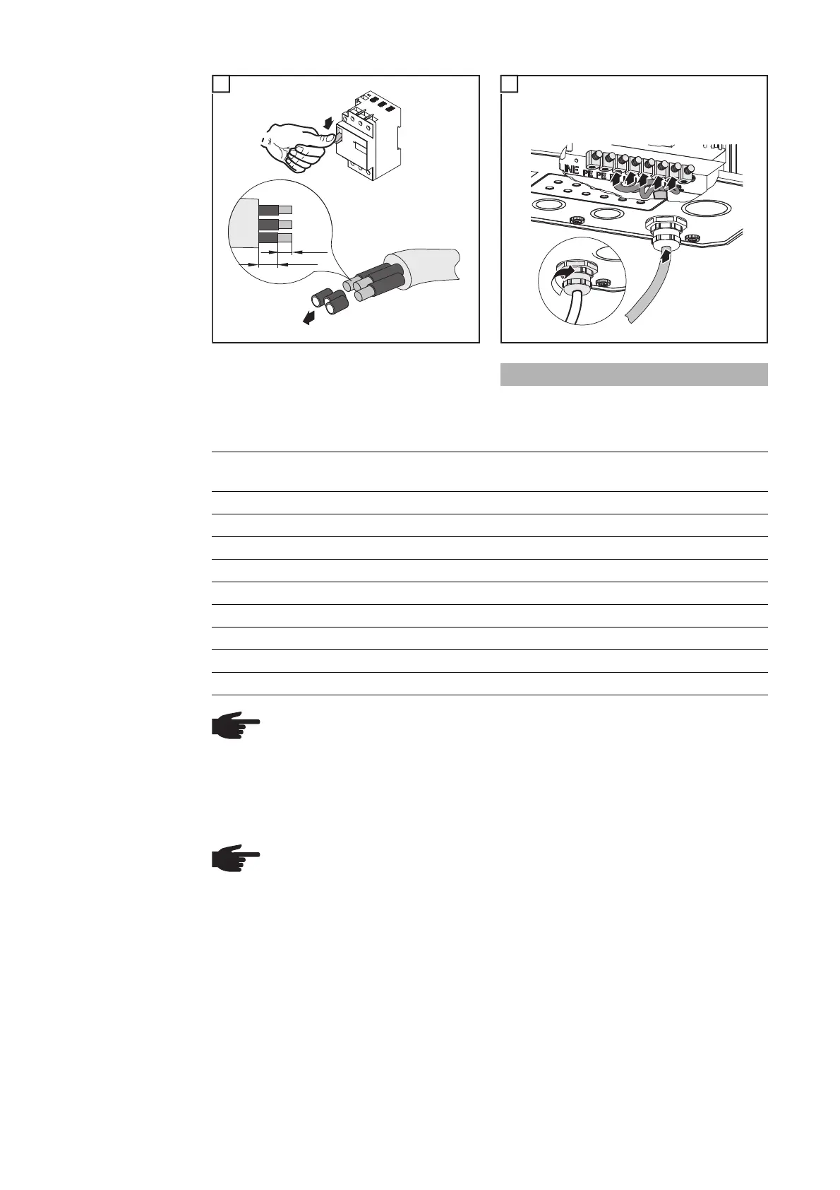
off
on
20 mm
10 mm
OFF
AC
2
1
2
Terminal tightening torque: 2 Nm
Inverter Number of
phases
Nominal output Fuse protection
Fronius IG Plus 30 V-1 1 3 kW 1 x C 20 A
Fronius IG Plus 35 V-1 1 3,5 kW 1 x C 20 A
Fronius IG Plus 50 V-1 1 4 kW 1 x C 25 A
Fronius IG Plus 70 V-1 1 6,5 kW 1 x C 40 A
Fronius IG Plus 70 V-2 2 6,5 kW 2 x C 20 A
Fronius IG Plus 100 V-1 1 8 kW 1 x C 50 A
Fronius IG Plus 100 V-2 2 8 kW 2 x C 25 A
Fronius IG Plus 120 V-3 3 10 kW 3 x C 20 A
Fronius IG Plus 150 V-3 3 12 kW 3 x C 25 A
NOTE! A residual current circuit breaker for the AC connecting cable may be re-
quired depending on local regulations, the power supply company as well as oth-
er conditions. A type A residual current circuit breaker is generally sufficient in this
case. However, false alarms can be triggered for the residual current circuit
breaker in individual cases and depending on local conditions. For this reason,
Fronius recommends that you use a residual current circuit breaker suitable for a
frequency converter.
NOTE! Three-phase inverters only: When using a residual current circuit breaker,
the voltage difference between the PE grounding conductor and the N neutral
conductor cannot be higher than 8 V.