Quick guide PV Point & PV Point Comfort 515
2 Installation
2.1 Hardware preparation
The installation of the PV Point [Comfort] requires a modication to the basic shell. Four predened
outputs are marked on the underside of the inverter for this purpose, which can be used for the PV Point
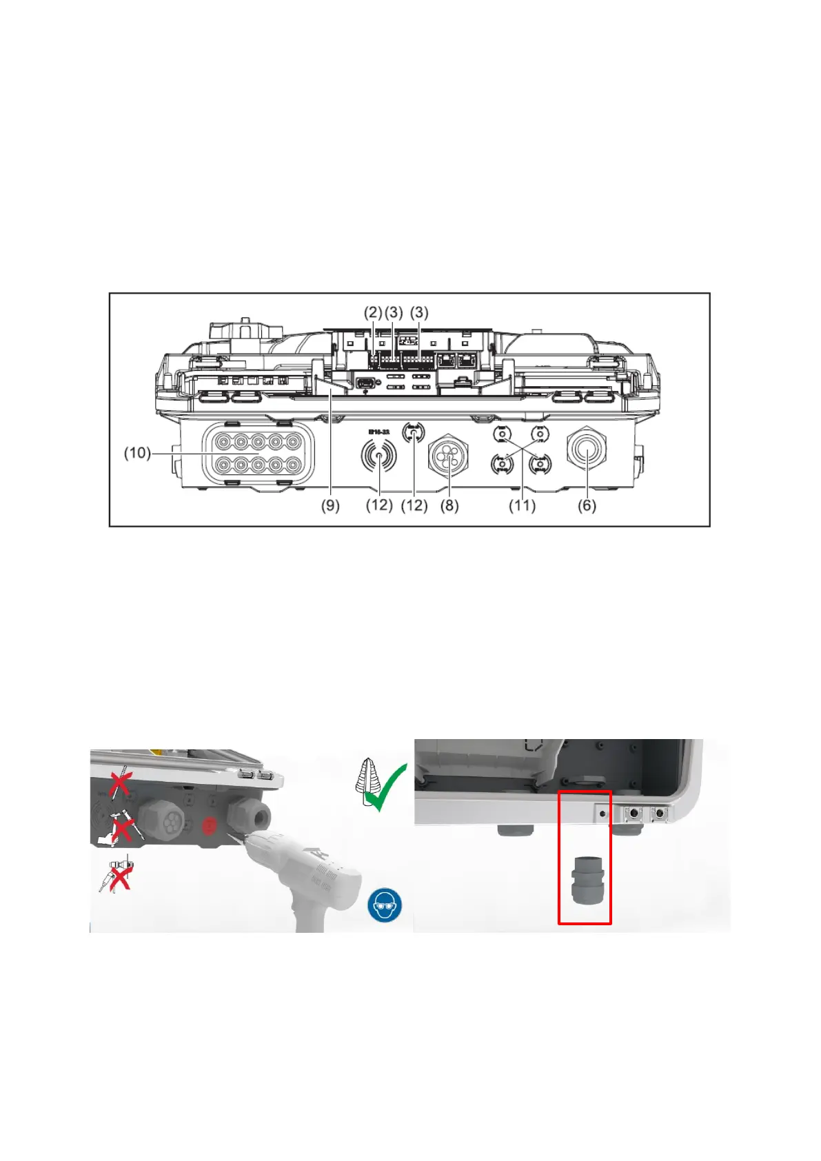
[Comfort] installation. The underside of the GEN24 series with the outputs is shown in Figure 2:
Figure 2: Inverter underside of the Fronius GEN24 & GEN24 Plus series with the four predened outputs
The rst step is to drill a hole through one of the four outlets on the base shell. We recommend using a
step drill (M16 / 16 mm diameter) for this. As soon as the hole has been drilled, a PG cable gland must
be tted to the drilled-through base shell in order to continue to ensure the highest protection class
IP66. Figure 3 shows the drilling process and the base shell with the PG cable gland inserted:
Figure 3: Drilling through the base shell and PG screw tting inserted at the drilled-through point