Quick guide PV Point & PV Point Comfort 615
2.2 PV Point cabling
Once the cable gland has been successfully inserted, the cable can be fed through and connected in the
inverter. In the GEN24 & GEN24 Plus series, a separate output / push-in spring-loaded terminal is
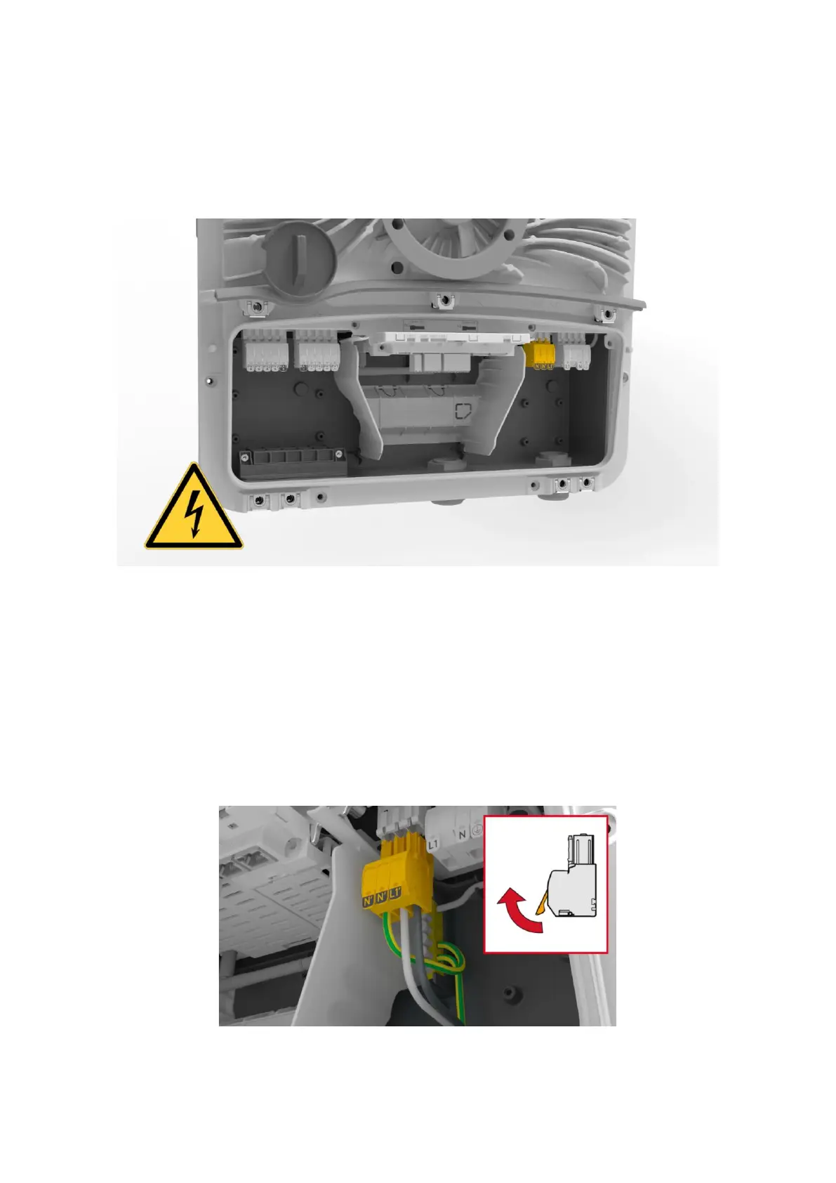
provided for the PV Point on the AC side, which is shown in Figure 4:
Figure 4: Connection area of the Fronius GEN24 & GEN24 Plus with PV Point Push-in spring clamp
The push-in spring terminals are characterized by their ease of use, which enables quick installation.
No special tools are required to install the PV Point and no ferrules need to be tted to the cables. With
regard to cables, Fronius recommends the use of a copper cable with a cable cross-section of min. 1.5
mm² to max. 10 mm² for direct connection. Figure 5 shows the requirements for the cable as well as
the handling and function of the spring-loaded terminals: