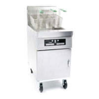
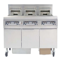
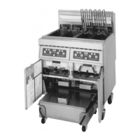
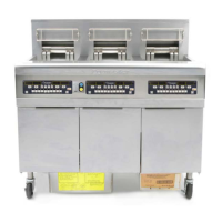
35 SERIES GAS FRYERS
CHAPTER 5: PREVENTIVE MAINTENANCE
5-5
5.3 Semi-Annual Checks and Service
Check Burner Manifold Pressure
WARNING
This task should be performed by qualified service personnel only.
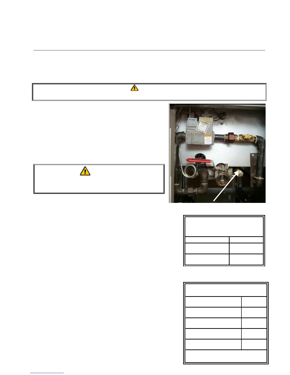
1. Ensure that the gas valve knob is in the OFF position.
2. Remove the pressure tap plug from burner manifold.
(see photo).
3. Insert the fitting for a gas-pressure measuring device
into the pressure tap hole.
4. Place the gas valve in the PILOT position and light. When the
burner lights and continues to burn, note gas pressure reading
and compare to the accompanying tables.
5. To adjust burner gas pressure, remove the cap from the gas
valve regulator adjustment screw.
6. Increase the setting on the thermostat until the burner comes on.
7. Monitor the gas pressure reading on the man-ometer or
pressure gauge.
8. Adjust the gas valve regulator adjustment screw to obtain the
prescribed pressure. See the Rating Plate. Turning the screw
clockwise increases pressure, counterclockwise decreases
pressure.
A manometer or water column pressure gauge
meter is connected to the manifold here.
Gas
(mbar)
Natural Gas Lacq
(G20) under 20 mbar
9
Natural Gas Groningue *
(G25) under 25 mbar
11
Natural Gas Groningue
(G20) under 20 mbar
11
Propane
(G31) under 37 or 50 mbar
22.5
CE Standard
Burner Manifold Gas Pressures
* Belgian specifications on 2-6
WARNING
The frypot must be filled with shortening or
water during this procedure.
Non-CE Standard
Burner Manifold Gas
Pressures
Gas Pressure
Natural 4.0" W.C.
0.73 kPa
LP 8.25" W.C.
2.05 kPa