LOV
™
Technical Reference
43
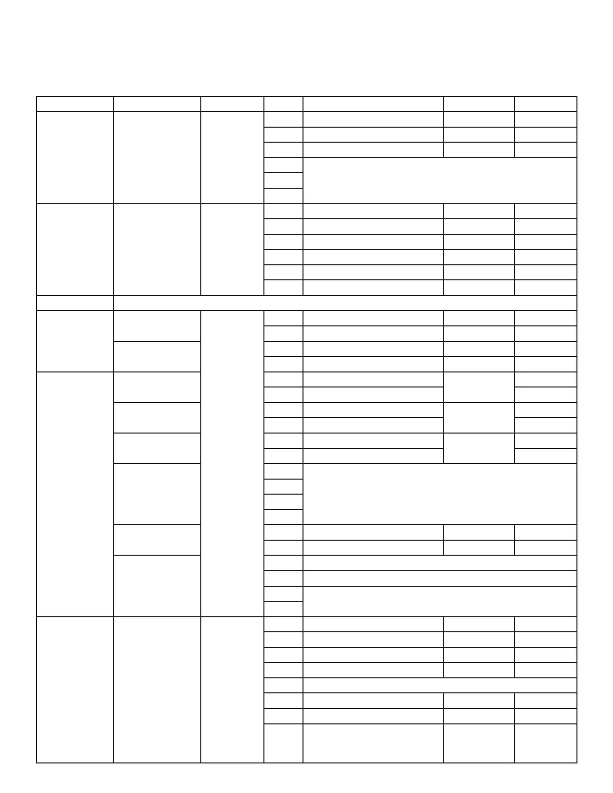
MIB (Manual Interface Board) Pin Positions and Harnesses
Connector From/To Harness # Pin # Function Voltage Wire Color
J1 M2007 J7 8074546
1 Ground Black
2 CAN Lo Red
3 CAN Hi White
4
5
6
J2 AIF J4 8074547
1 Ground Black
2 CAN Lo Red
3 CAN Hi White
4 5VDC+ 5VDC Black
5 24VDC 24VDC Red
6 Ground White
J3 SD Card
J4
RTI - JIB Fill
Switch
8074649
1 Momentary Switch - Out 5VDC Red
2 Momentary Switch - In 5VDC Black
Reset Switch
3 Ground Red
4 Reset Green
J5
Transformer
1 24VAC
24VAC
Black
2 24VAC Ret White
Filter Relay
3 Pump Motor
24VDC
Red
4 Pump Motor Green
Blue LED
5 Blue LED +
24VDC
Black
6 Blue LED - White
7
8
9
10
Pan Switch
11 Pan Sw + 24VDC Black
12 Pan Sw - Red
13 Ground
14 Ground
15
16
J6
RTI - Pump &
Solenoids
1 From RTI transformer 24VAC Black
2 Common White
3 To RTI “Add Pump” Relay 24VAC Green
4 To Waste Solenoid - 3 Way 24VAC Brown
5
6 To Fill Solenoid - 3 Way 24VAC Black
7 Ground - Fill Solenoid Black
8
From RTI “Waste Tank Full
Sensor” Test Pins 1 to 8
0VDC – Full
5VDC – Not
Full
Red