Section 3 Mechanical Installation & Lightning Protection
29 FT722 & FT742 (RS485) – FF & PM Sensors – User Manual
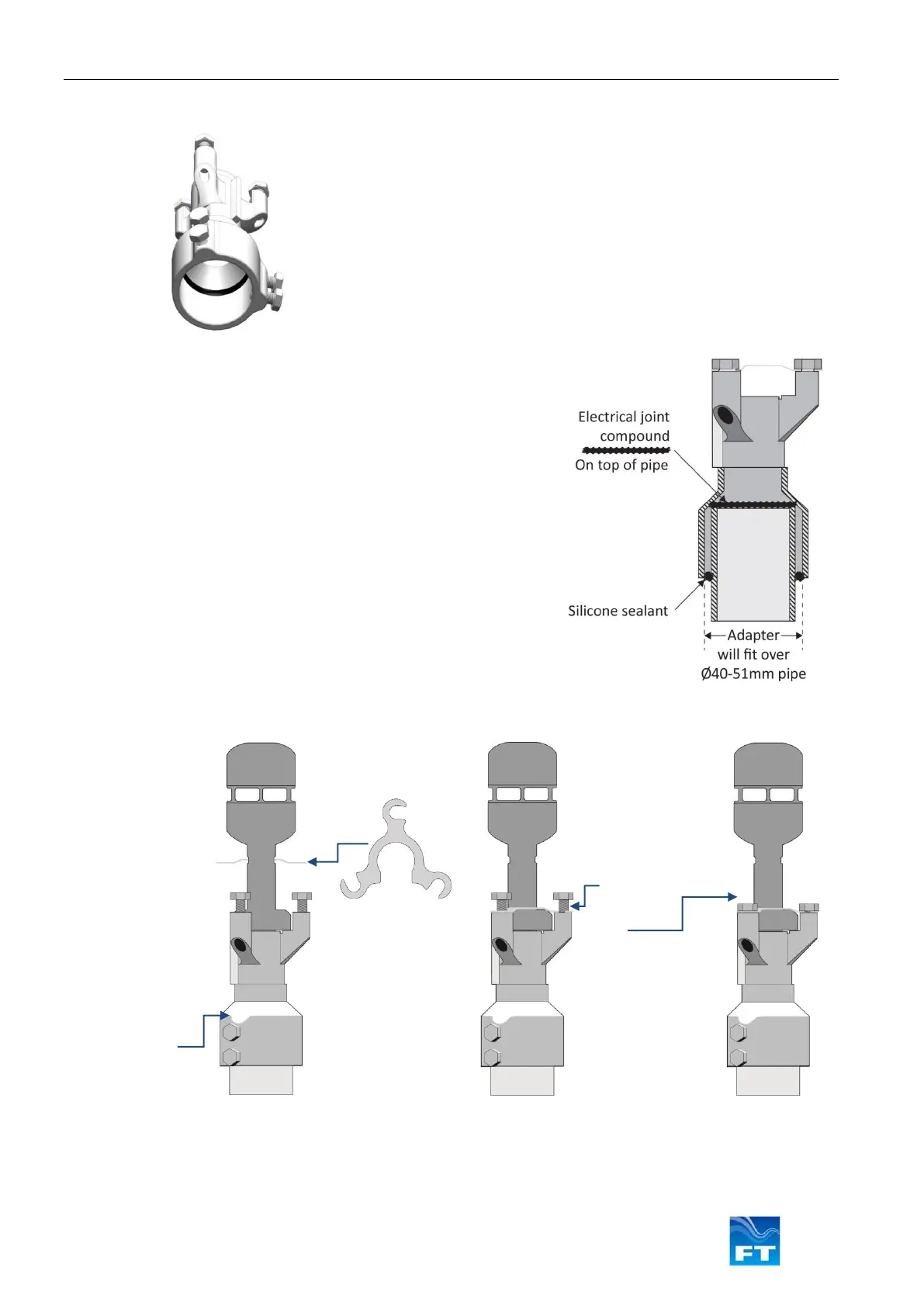
3.2.2 Assembling the Pipe Mount Adapter
Securing the
Sensor
i)
Remove any
connector
protection
caps and mate
the cable and
sensor
connectors.
j)
Place the
sensor on top
of the adapter,
orientated on
the datum
feature
k)
Slide the
bracket over
the notch on
the wind
sensor.
l)
Slide the
bracket
down to the
base and
rotate it so
that it lines
up under the
M8 bolts.
m)
Tighten the 3
M8 bolts to
secure the
sensor to the
adapter,
preventing
any
movement.
Figure 22: Sensor Installation Instructions
Figure 20: Preparing the Adapter
The adapter should be fitted onto a pipe with an outer diameter
of 40-51mm.
The pipe end is to be 172 mm below the desired measuring point;
the mid-point of the sensor’s measurement cavity.
Run the sensor cable up through the pipe and through the
adapter (which should not be fitted to the pipe yet) and secure it
so that it cannot fall back down inside.
Figure 21: Installing the Adapter
Apply a liberal amount of electrical joint compound to the top
surface of the pipe
Place the adapter on top of the pipe. A spirit bubble can be
used to ensure the installation is flat.
Rotate the adapter to align the datum feature as required. The
datum feature should be at the back of the wind sensor, with
respect to the wind direction. A laser alignment tool could be
used to ensure accuracy of alignment.
Tighten the 4x M8 bolts to fix the adapter securely in position
If a gap exists between the side of the pipe and the bottom
edge of the adaptor, sealing can be further improved by
applying silicone sealant. Suitable sealants could be either
Dow Corning 790 Silicone Building or Pecora 864 Silicone
Sealant.