Section 1 Introduction
7 FT722 & FT742 (RS485) – FF & PM Sensors – User Manual
1 INTRODUCTION
1.1 Product Overview
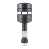
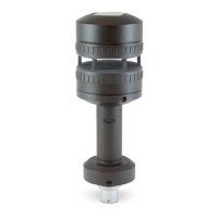
The FT722 and FT742 are solid-state ultrasonic wind sensors using a patented Acoustic Resonance
airflow sensing technique to measure accurately both wind speed and direction. The sensors have been
specifically designed to operate in harsh environments including offshore, lightning and ice-prone areas.
The wind sensor has no moving parts to degrade or wear-out and is designed for applications requiring
high reliability. They help reduce costly down-time and unscheduled maintenance visits.
Mounting and aligning the sensor is very simple. A 0° wind datum marking can be used to align the
sensor to a reference point. For operation in ice-prone areas, the FT722 and FT742 are fitted with a
highly-effective thermostatically controlled all-body heating system. A three element heater is used to
ensure heat is evenly distributed over the entire surface area.
1.2 Build Versions and Labelling
The electrical interface is the same as our previous range of FT702LT (RS485) sensors. The same pin-
outs and RS485 communication standard is used.
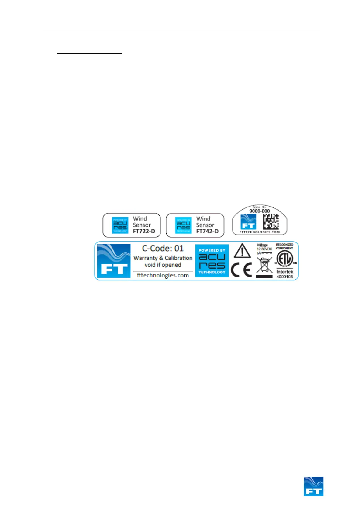
Figure 1 shows how to identify the sensor platform version and individual serial number, depending on
the attached main labels:
Additional labels may be attached. Only sensors marked with the Intertek label conform to the UL Standard
61010-1 and are certified to CSA Standard C22.2 No. 61010-1.
Figure 1: Examples of Main Sensor Labels
1.3 Scope of Use
The sensor is designed, manufactured and optimised for high availability.
No promise in part or full can be given to guarantee a sensor’s continuous operation, as exceptional
circumstances can occur that may result in the failure of the output from a sensor. Exceptional
circumstances can include:
• Poor installation
• Inadequate inspection
• Power supply failures
• Poor quality electrical connections
• Lightning exposure
• Problematic environmental conditions or combination of conditions
• Physical Damage
Typically higher levels of wind speed and wind direction data availability are achieved through the use
of an additional FT sensor or alternative sensor. Control strategies or algorithms, which compensate in
whole or in part, for any temporary interruption of data from individual sensors should also be applied.
The choice and implementation of such methods is entirely the Purchaser’s responsibility.