Section 5 Sensor Communication
52 FT722 & FT742 (RS485) – FF & PM Sensors – User Manual
5.4.4 Listener and Talker Identifiers
The sensor is assigned with both a Listener and Talker identifier address that allows an individual sensor to be
uniquely identified in a system comprising more than one sensor.
Whenever a message is sent to the sensor, the identifier field of the message (the 2 characters immediately
following the ‘$’ start of message character) must correspond to the sensor Listener identifier address, otherwise
the sensor will ignore the message. In applications where more than one sensor is connected to the RS485 bus,
you should assign each sensor in the system a unique Listener ID. The host computer will then be able to address
individually each sensor. If you do not wish to use the Listener ID in messages sent from the host computer, you
can replace the Listener ID with ‘//’. Sending ‘//’ in place of the Listener ID will allow any sensor, irrespective of its
Listener ID setting, to respond to the message.
Whenever a message is transmitted from the sensor, the identifier field of the message (the 2 characters
immediately following the ‘$’ start of message character) will contain the Talker ID. The Talker ID is used as a
message tag to identify which sensor has transmitted the message.
The factory default value for the Listener ID is 01 and for the Talker ID it is WI (Weather Instrument). To change
the Listener and/or Talker ID use the ID Command, Section 6.4.18.
Note: It is important to use the correct listener IDs for the system. Incorrect serial IDs will fail to communicate with
the controller. For example, repair technicians may incorrectly believe the sensor is faulty.
5.4.5 Calculating the Message Checksum
All messages sent to, or received from, the sensor include a checksum field. Messages that are transmitted from
the sensor always include a checksum value in the checksum field. Messages sent to the sensor by the host
computer can either contain a checksum value or an ‘ignore checksum identifier’ in the checksum field.
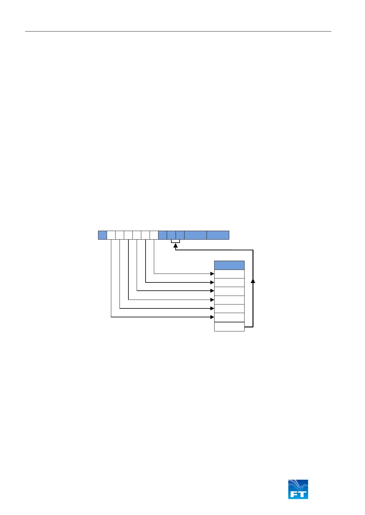
The checksum value is calculated by Exclusive OR’ing (XOR’ing) all the bytes between (but not including) the ‘$’
and the ‘*’ characters of the message. The resulting single byte value is then represented by 2 HEX characters in
the message string. The most significant character is transmitted first.
Note: Since a message only contains ASCII characters (which have values in the range 0-7F) the checksum value
will always be between 0 and 7F.
5.4.6 Disabling the Checksum
All messages which are sent to the sensor must contain a valid checksum value in the checksum field, otherwise
the sensor will not process the incoming message. Although it is recommended that a checksum value be
computed for all messages which are sent to the sensor, in some cases this may not be convenient (i.e. when
communicating with the sensor with a terminal). To prevent the sensor from performing checksum validation of
incoming messages, send the ASCII characters ‘//’ in place of the checksum value.