Section 4 Service, Configuration & Testing
41 FT722 & FT742 (RS485) – FF & PM Sensors – User Manual
4.4.1 Software Installation
1. Insert the Acu-Vis 2.0 CD into the PC. Begin the installation by running the setup.exe file, it may be
necessary to contact an IT administrator. Follow the on-screen instructions.
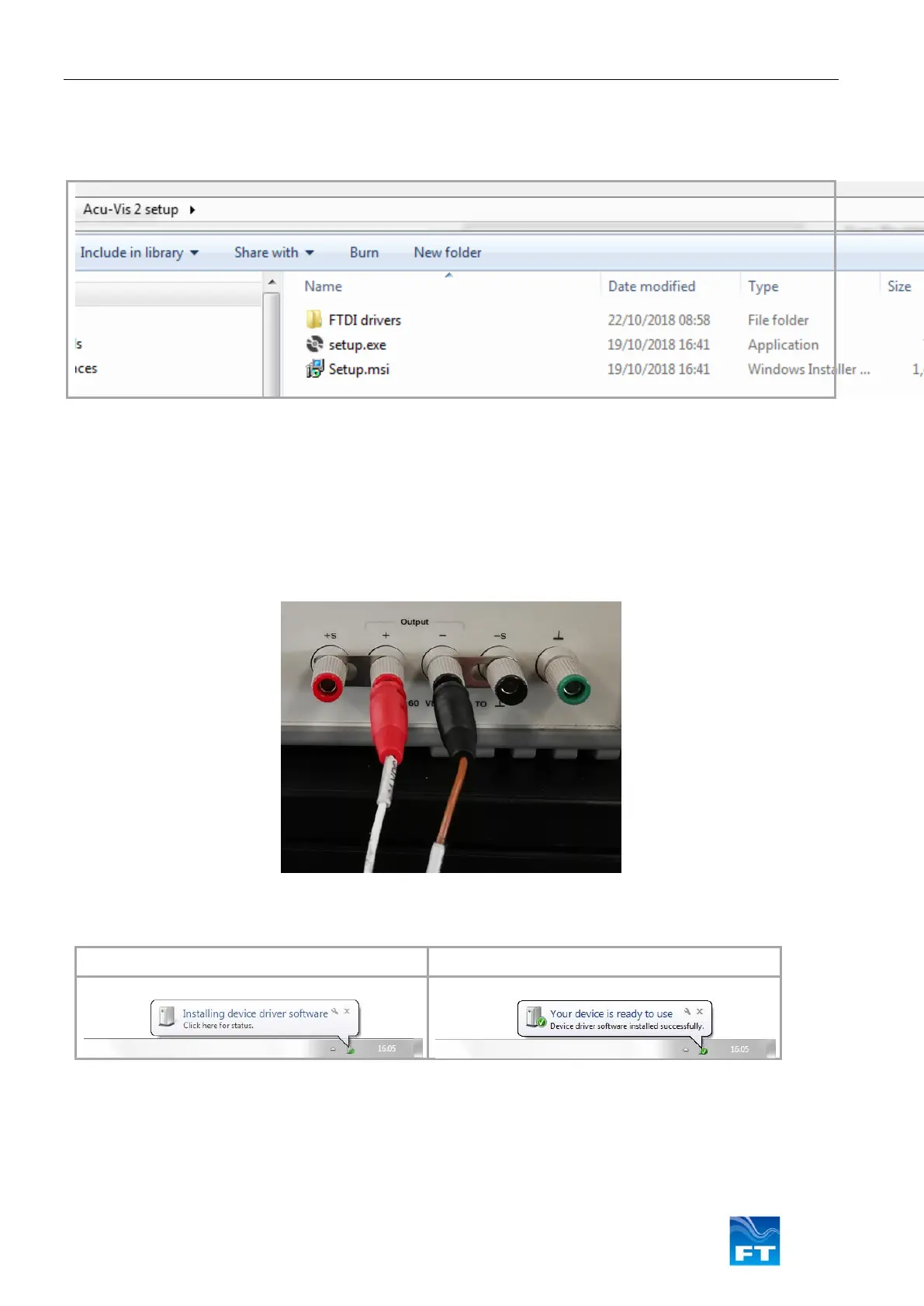
Figure 35: Acu-Vis Install Files
2. Remove the FT742 sensor and USB test cable from their packaging
3. Ensure the power supply is disabled
4. Connect the test cable to the relevant parts: Connect the +24VDC terminal of the power supply to the
white wire (red test plug) and 0V terminal to the brown wire (black test plug). Connect the USB to a
spare USB PC socket and remove any unnecessary USB devices
Figure 36: Acu-Test Cable Power Connections
5. Windows will automatically detect the USB cable and attempt to update the FTDI drivers
Please wait for Windows to install the hardware
Figure 37: Windows driver installation sequence
6. When the user is ready to operate the sensor - enable the power. When using a benchtop PSU ensure
the required voltage is supplied (6-30VDC) and the current output is enabled